Honeywell Thermostat Y594 User Manual

File Preview
Click below to download for free
Click below to download for free
File Data
| Name | honeywell-thermostat-y594-user-manual-1307864952.pdf |
|---|---|
| Type | |
| Size | 797.54 KB |
| Downloads |
Text Preview
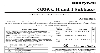
Y594 Thermostat Subbase INSTRUCTIONS Ratings RATING 7.5A inrush 2.5A running at 30 Vac Designed for mounting on wall or horizontal box Y594G and Y594J combination packs are designed meet the specific requirements of Carrier heat pump The Y594 packs are designed for 2 stage heat 1 stage cool applications The system switch is SUPL or SUPL HT ON OFF The fan is AUTO ON See Table 1 for model information cross reference from Carrier part numbers 1 Heat Pump Thermostat Subbase Combinations No Honeywell T874G1055 Carrier HH07AT171 T874G1055 HH07AT171 or or or or in in in in Ratings sealed mercury switch RATINGS Stage Heating and Cooling 6.5A inrush 1.5A running at 25 Vac Stage Heating and Cooling 1.5A maximum at 30 Vac Switch 6.5A inrush 1.5A running at 25 ANTICIPATOR Stage Heating and Cooling fixed voltage type Stage Heating adjustable 0.10 to 1.2A other SETTING RANGE 42 to 88 6 to fixed voltage type 1.0A two stages of heat are energized sequentially with in temperature Stage one comes on first then if temperature at the thermostat continues to move away the setpoint the second stage comes on The is set with about 2 1 between stages As heating equipment runs and the temperature begins to back toward the set point stage 2 goes off first then one include an LED light emitting diode indicator indicator lights to show that the heat pump cannot and the supplemental heat stage is providing all This condition can occur in two instances when subbase system switch is set at SUPL HT and when heat pump compressor has malfunctioned LEDs are not field replaceable 1995 Honeywell Inc All Rights Reserved UL MULTISTAGE THERMOSTAT SUBBASE PACKAGE NOTICE control contains mercury in a sealed tube not place control in the trash at the end of its life this control is replacing a control that contains in a sealed tube do not place your old in the trash your local waste management authority for regarding recycling and the proper of this control or of an old control mercury in a sealed tube Installing this Product Read these instructions carefully Failure to follow could damage the product or cause a hazard condition Check the ratings given in the instructions and on product to make sure the product is suitable for application Installer must be a trained experienced service After installation is complete check out product as provided in these instructions Disconnect power supply to prevent electrical or equipment damage Run wires as close as possible to the sub To prevent interference with the linkage keep wire length to a Push excess wire back into the and plug hole to prevent drafts from thermostat operation Do not overtighten thermostat captive screws because damage to threads can result Do not short across coil terminals on relay may burn out the heat anticipator Never install more than one wire per terminal factory supplied jumper with spade is used and Wiring the Subbase power supply to prevent electrical shock or damage All wiring must comply with local codes and ordinances Follow equipment wiring instructions when available the subbase on a wall or horizontal outlet box To it on a vertical outlet box order Honeywell part no Cover Plate Assembly which includes an ring with two screws for vertical outlet box and a cover plate to cover marks on the wall install subbase proceed as follows Prepare a hole for the thermostat wires at the location Run wires to location Pull about 6 in 152 mm of wire through the hole 18 gauge color coded thermostat cable for wiring If mounting the subbase on a vertical outlet box adapter ring with the two screws provided in assembly See Fig 1 Pull wire through cover plate if used and subbase opening Secure the cover plate and subbase the two screws provided but do not tighten Level the subbase using a spirit level See Fig 2 subbase mounting screws The subbase slots provide for minor out of level incorrectly leveled subbase will cause the control to deviate from setpoint Connect the system wires to the subbase See 4 7 A letter is stamped near each terminal for The terminal barrier permits straight or wraparound wiring connections See 3 Either method is acceptable Run wires as as possible to the subbase keeping wire to a minimum Push excess wire back into Plug hole to prevent drafts are calibrated at the factory by using mounted at true level Inaccurate sub leveling will cause thermostat control the Thermostat Remove the thermostat cover by pulling the bottom of the cover away from the base until it snaps of the retaining posts the thermostat about 5 ft 1.5m above the floor in area with good air circulation at average room not mount the thermostat where it may be affected by drafts or dead spots no air movement behind doors corners and above or below shelves hot or cold air from ducts radiant heat from the sun lights or appliances concealed pipes and chimneys unheated or uncooled areas such as an outside wall the thermostat The cover is hinged at the top and must be by pulling out at the bottom Carefully remove and discard the polystyrene insert that protects the mercury switches shipment Turn the thermostat over and locate the spring that engage the subbase contacts Make the spring fingers are NOT bent flat preventing electrical contact with the subbase Set adjustable heat anticipator indicators if as described in Setting the Heat section MULTISTAGE THERMOSTAT SUBBASE PACKAGE 2 60 70 80 SCREWS 2 60 70 80 SCREWS 2 NOT INCLUDED WITH UNIT 60 70 80 ACCESSORY PARTS AVAILABLE 193121A 1 Installation of subbases and thermostat on box LEVEL 2 OPENING 2 2 FOR SPRING FINGER ON THE TO 12 2 Leveling the subbase STRAIGHT 5 16 in 8 mm WRAPAROUND 7 16 in 11 mm TERMINAL SCREW 3 Wiring connections Note the tabs along the top inside edge of the base The tabs fit into the subbase Mount the thermostat on the subbase and the captive mounting screws See Fig 1 Do overtighten captive mounting screws This can the threads in the subbase Place the upper edge of the thermostat cover on the and swing cover downward until it engages posts on base Tighten the locking cover if assembly is provided the 2nd Stage Y594G1666 and Only Heat Anticipator the adjustable heat anticipator to match its primary control draw If the primary control nameplate has no rating or further adjustment is necessary use the following procedure measure the current draw of each stage Remove thermostat from the subbase Make sure power is on Connect an ac ammeter of appropriate range the heating terminals of the subbase 2 between W2 and R Move the system switch to HEAT