Honeywell Thermostat Y8196A User Manual

File Preview
Click below to download for free
Click below to download for free
File Data
| Name | honeywell-thermostat-y8196a-user-manual-0621547398.pdf |
|---|---|
| Type | |
| Size | 789.25 KB |
| Downloads |
Text Preview
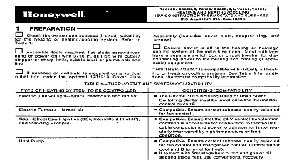
Y8196A T8196A Thermostat Subbase Heating Cooling New Thermostat Subbase Instructions thermostat and subbase suitability for the heat cooling or heating cooling system Refer to Table 1 tools required flat bladed screwdriver hand power drill with 3 16 in drill bit wire cutter stripper or knife bubble level or plumb bob and line power is off to the heating cooling or heating system at the main fuse panel Most buildings have separate switch box or circuit breaker for disconnecting to the heating and cooling if applicable equipment thermostat is compatible with virtually all heating or heating cooling systems Refer to Table 1 for thermostat compatibility information 1 AND SYSTEM COMPATIBILITY of Heating System be Controlled Line Voltage baseboard and Spark Ignition DSI Intermittent IP and Standing Pilot SP Pump Water Zone Damper The R8239D1015 Isolating Relay or R841 Silent Switching must be installed in the thermostat control circuit a Compatible Compatible Assure correct subbase identity is selected for fan and changeover control O terminal for cool and B for heat Jumper Y to W for heat pump compressor Honeywell 2 wire valves are compatible Some non Honeywell 2 wire valves require an R8239D1015 Relay in the thermostat control circuit a Some 3 wire valves require an R8239A1052 Isolating Relay the thermostat control circuit a b Compatible Honeywell damper motors are compatible Some non Honeywell damper motors require an R8239D1015 Relay in the thermostat control circuit a Check amperage requirement Air Zone If thermostat is not compatible with the system being controlled the system will not operate No hazard exists The thermostat not be damaged unless it is used to directly control a line voltage system A Honeywell R841 or R8239D1015 Isolating must be added to the thermostat control circuit for proper system operation Most are compatible Consult manufacturer for installation requirements Notice control contains mercury in a sealed tube Do not control in the trash at the end of its useful life this control is replacing a control that contains mer in a sealed tube do not place your old control in the your local waste management authority for regarding recycling and the proper disposal of control or of an old control containing mercury in a tube F Rev 12 94 Inc 1994 Form Number 69 0637 1 thermostat MOUNTING INSTALLING THIS PRODUCT Read these instructions carefully Failure to follow could cause a hazardous condition Installer must be a trained experienced service techni After installation is complete check out product op as provided in these instructions An incorrectly leveled subbase will cause temperature control to deviate from setpoint It is a calibration problem 1 12 BASE Disconnect power supply to prevent electri shock or equipment damage To prevent interference with the thermostat keep wire length to a minimum and wires as close as possible to the subbase Do not overtighten thermostat captive mount screws because damage to subbase can result Do not short across coil terminals on relay can burn out the thermostat heat an thermostat about 5 ft 1.5m above the floor in an with good air circulation at average temperature Do mount the thermostat where it may be affected by drafts or dead spots behind doors and in corners hot or cold air from ducts radiant heat from the sun or appliances concealed pipes and chimneys unheated uncooled areas such as an outside wall the thermostat wires from the heating cooling or heating cooling to the new thermostat location THERMOSTAT your new thermostat carefully rough handling interfere with its accuracy Before unpacking refer to 1 and discard the shipping wrap Save package of screws and instructions the homeowner the thermostat cover by lifting from the bottom aside cover until needed later remove the material protecting the mercury bulb two captive mounting screws SUBBASE Mounting Fig 2 the subbase in position on wall Fig 2 holes on the wall for anchors Use spirit level to sure the wallplate or subbase is level 3 16 in holes and gently tap anchors into holes flush with the wall wires through the large wiring hole in the subbase fasten the subbase to the wall with the three Do not completely tighten the screws level the subbase Fig 3 and firmly tighten screws 2 subbase to wall SCREW HOLES PLASTIC SUBBASE Box Mounting Fig 4 a horizontally mounted outlet box if possible If a outlet box is used the subbase must be mounted on 202689A Cover Plate Assembly ordered separately the instructions provided with the cover plate as the subbase mounting holes on the outlet box and fasten with the two screws level the subbase Fig 3 and firmly tighten screws 3 methods for subbase LEVEL OR 4 subbase on outlet box BOX OR INCLUDED WITH UNIT PARTS AVAILABLE 2 SUBBASE the instructions provided by the heating cool or heating cooling equipment manufacturer If not refer to the Typical Wiring Diagrams section at end of this publication the power supply before making wiring con to prevent electrical shock or equipment damage All wiring must comply with local electrical codes ordinances to Fig 5 and strip thermostat wire insulation as 5 of connecting terminals STRAIGHT 5 16 in 8 mm WRAPAROUND 7 16 in 11 mm the wires to corresponding terminals on the labels do not agree with your new subbase refer to 2 or Fig 11 2 DESIGNATIONS Function transformer power control circuit control circuit jumper to W for pump compressor control control circuit damper or changeover reversing makes continuously in cool damper or changeover reversing makes continuously in heat excess wire back into the wall the hole in the wall with nonhardening caulk putty nonflammable insulation to prevent drafts from affect thermostat operation THE THERMOSTAT the tabs on the top inside edge of the thermostat These tabs fit the slots molded into the top of the thermostat base on subbase the two captive mounting screws located in the corners of the base Fig 6 tighten the screws 6 mounting TIMER the timer by moving the knob clockwise NOT reverse the knob time is correctly set the time indicator arrow Fig 8 must point to the corresponding daytime light or dark portion of the program dial 8 timer 2 SLOT 2 1 12 SUBBASE SCREWS TIMER BATTERIES is supplied to the timer by two AAA alkaline not included the batteries in the thermostat Fig 7