Honeywell VisionPRO TH8000 Series Installation Manual

File Preview
Click below to download for free
Click below to download for free
File Data
| Name | honeywell-visionpro-th8000-series-installation-manual-3089541627.pdf |
|---|---|
| Type | |
| Size | 1.13 MB |
| Downloads |
Text Preview
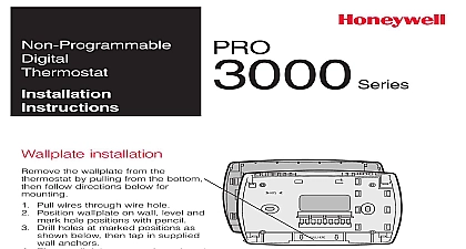
Installation TH8000 Series Programmable Thermostat manual covers the following models TH8321U1097 For up to 3 Heat 2 Cool heat pump or up to 2 Heat 2 Cool systems with dehumidification humidification or ventilation thermostat from wallplate and turn over to find model number be installed by a trained experienced technician Read damage the product or cause a hazardous condition ELECTRICAL HAZARD cause electrical shock or equipment damage Disconnect power before installation NOTICE this product is replacing a control that contains mercury in a sealed tube do not the old control in the trash Contact your local waste management authority for regarding recycling and proper disposal thermostat contains a Lithium battery which may contain Perchlorate material Material handling may apply www dtsc ca gov hazardouswaste perchlorate Help assistance with this product please visit http customer honeywell com call Honeywell Customer Care toll free at 1 800 468 1502 U S Registered Trademark Patent No 6595430 D509151 and other patents pending 2011 Honeywell International Inc rights reserved Guide installation Separate wallplate from thermostat Mount wallplate as shown below top and bottom of wallplate pull to remove from thermostat 3 16 holes for drywall 7 32 holes for plaster hole screws anchors TH8000 Series 24VAC primary power connect common of transformer to terminal supplied batteries for or backup power excess wire back into the wall opening Plug opening with non flammable insulation options Designations Terminal Letters power Connect to secondary of system transformer wire from secondary side of stage heat relay stage heat relay stage compressor contactor stage compressor contactor relay Optional outdoor remote discharge Optional IAQ device Pump Terminal Letters power Connect to secondary of system transformer wire from secondary side of transformer stage compressor contactor stage compressor contactor Auxiliary Emergency heat relay relay pump reset powered when System is set to Heat system monitor when set to Cool or Off valve for heat pumps Optional outdoor remote discharge Optional IAQ device System 1 transformer System 1 transformer guide systems Guide 1 6 relay contactor relay common 2 Optional outdoor remote discharge Optional IAQ relay Only System 1 relay common 2 Optional outdoor remote discharge Optional IAQ relay Only System Series 20 20 valve terminal 1 20 valve terminal 20 valve terminal common 2 Optional outdoor remote discharge Optional IAQ relay relay 2 relay 2 1 6 relay 1 relay 1 relay common 2 Optional outdoor remote discharge Optional IAQ relay Only System With Fan 1 6 relay relay common 2 Optional outdoor remote discharge Optional IAQ relay Only System 1 contactor relay common 2 Optional outdoor remote discharge Optional IAQ relay notes below 1 Power supply Provide disconnect means and overload protection as required 2 Optional 24VAC common connection 6 Only works with single transformer systems Heat Pump no auxiliary heat Heat Pump no auxiliary heat guide pump systems TH8000 Series 1 valve 3 relay relay common 2 Optional outdoor remote discharge Optional IAQ relay Heat Pump with auxiliary heat monitor 4 5 Auxiliary emergency heat relay Optional outdoor remote discharge 1 valve 3 relay relay common 2 4 Optional IAQ relay humidifier or any humidifier with own transformer 1 relay 7 relay 7 house dehumidifier 1 relay 7 relay 7 1 relay 7 relay 7 2 relay 1 valve 3 1 relay relay common 2 Optional outdoor remote discharge Optional IAQ relay Heat Pump with auxiliary heat 2 relay monitor 4 5 Auxiliary Emergency heat relay Optional outdoor remote discharge 1 valve 3 1 relay relay common 2 4 Optional IAQ relay flow through humidifier or any that uses the system trans 1 jumper R to U1 7 relay 7 1 jumper R to U1 7 relay 8 1 jumper R to U1 7 relay guide systems guide systems with low speed fan house powered ventilator ventilator guide systems notes below 1 Power supply Provide disconnect means and overload protection as required 2 Optional 24VAC common connection 3 O B set to control as either O or B in installer setup 4 If L terminal is used 24VAC common terminal C must be connected 5 Heat pump reset powered continuously when thermostat is set to Em Heat system monitor set to Heat Cool or Off 7 Terminals are normally open dry contacts 8 Equipment must include dehumidification terminal for low speed fan Guide tab and mount thermostat tab pins on back of thermostat with in wallplate then push gently thermostat snaps into place st set time date and time st set date st set month st set year DONE to save changes setup Press SYSTEM Press and hold for 5 seconds Change settings see p 7 9 s t to change DONE to save and exit DONE to save exit TH8000 Series setup functions two digits two digits format energy saving type Pump Type control valve terminal heat fossil kit stage com cycle rate stage com cycle rate stage heat rate CPH per hour stage heat cycle CPH stage heat rate CPH options 00 99 options 1 12 options 1 31 programming Options factory default in bold Non programmable No heat 1 cool conventional heat 1 cool heat pump no aux heat only 2 wire systems only with fan water Series 20 system power to open close zone open zone valves only heat 1 cool heat pump with aux heat heat 2 cool multistage conventional heat 1 cool multistage c