Kidde 3101030-EN R04 FSUIM Universal Interface Module Installation Sheet

File Preview
Click below to download for free
Click below to download for free
File Data
| Name | kidde-3101030-en-r04-fsuim-universal-interface-module-installation-sheet-5923164087.pdf |
|---|---|
| Type | |
| Size | 874.16 KB |
| Downloads |
Text Preview
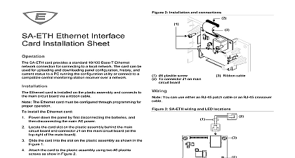
Legend for Figure 1 All wiring is supervised and power limited unless noted otherwise Only the trouble relay and power relay are energized when power applied AUX power supplied by the control panel can exceed 0.5 A If than 0.5 A is required you must use a power limited and 24 VDC auxiliary booster power supply that is UL ULC for fire protective signaling systems powered from an external supply the supply must be installed the same room as the control panel and their 24 VDC wired together Relay outputs are not supervised and do not provide current Connect relays only to power limited sources Use momentary switches only Mount LEDs and switches in separate cabinet located in the same as the FSUIM capacitance resistance fault impedance 0 inputs Quantity Wiring Class outputs Quantity rating Wiring Class size environment humidity resistor to 27.3 VDC mA mA max max B k 1 2 W C Vdc at 1 A resistive load E to 18 AWG 0.75 to 2.5 mm cabinet to 49 32 to 120 to 93 noncondensing information contact information see www edwardsfiresafety com Universal Interface Installation Sheet FSUIM Universal Interface Module provides five common control inputs and nine common relay outputs Typically the FSUIM is in a graphic annunciator connected to an F series fire alarm panel provide visual indication when a relay is energized FSUIM is shipped with a plastic snap track for mounting in an cabinet the FSUIM according to the instructions provided below The will not operate properly until detected by the control panel can only install one FSUIM per system more information refer to the technical reference manual listed the control panel door Make sure all power is disconnected from the panel before Observe static sensitive handling practices install the FSUIM Mount the snap track in the MFC A cabinet as shown in Figure 1 can also mount the snap track vertically if required the bottom edge of the FSUIM into the snap track then press top edge in until it snaps into place Wire the FSUIM as shown in Figure 1 Verify that all wiring is free opens shorts and ground faults 2016 United Technologies Corporation 2 3101030 EN REV 04 ISS 21SEP16 1 Typical installation wiring Fault Silence Silence Test Silence Silence 2 3101030 EN REV 04 ISS 21SEP16