Kidde 3101032-EN R03 FSRZI-A(-SA) Remote Zone Indicators Installation Sheet

File Preview
Click below to download for free
Click below to download for free
File Data
| Name | kidde-3101032-en-r03-fsrzi-a-sa-remote-zone-indicators-installation-sheet-2097538416.pdf |
|---|---|
| Type | |
| Size | 656.18 KB |
| Downloads |
Text Preview
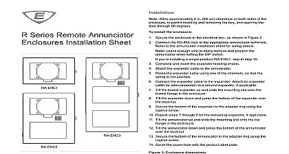
Installation Make sure all power is disconnected from the panel before Observe static sensitive handling practices more information refer to the technical reference manual listed the control panel door install the remote zone indicator Configure the jumpers as described in Table 1 and Verify that all field wiring is free of opens shorts and ground 2 Wire the remote zone indicator as shown Figure 1 Mount the remote zone indicator in the electrical box using the two machine screws See Figure 2 If you are surface mounting the remote zone indicator you install washers provided between it and the surface mount Attach the faceplate to the remote zone indicator Use the two machine screws provided with the faceplate Remote zone indicators will not operate properly until detected the control panel For more information see the technical reference listed inside the control panel door remote 1 Wiring diagram panel 24 VDC control panel or power supply 3 All wiring is supervised and power limited AUX power supplied by the control panel can exceed 0.5 A If than 0.5 A is required you must use a power limited and 24 VDC auxiliary booster power supply that is UL ULC for fire protective signaling systems If powered from an external supply the supply must be installed in same room as the control panel and their 24 VDC commons wired together Remote Zone Installation Sheet FSRZI A and FSRZI SA are remote zone indicators for F Series alarm control panels The FSRZI A provides five red LEDs for alarm zones The FSRZI SA provides five bi color LEDs red alarm zones yellow for supervisory and monitor zones jumpers determine which zones are indicated and FSRZI SA remote zone indicators include a cover plate installation in a standard single gang electrical box You can install or two FSRZI A and FSRZI SA remote zone indicators with or an FSRSI remote system indicator in an approved 2 3 or 4 electrical box Cover plates for 2 3 and 4 gang electrical boxes numbers FSAT2 FSAT3 and FSAT4 are ordered separately paper insert is provided for creating custom LED labels and FSRZI SA remote zone indicators are configured using jumpers described in the tables below peripheral group 1 peripheral group 2 1 Group selection jumper Only two remote zone indicators are allowed per peripheral 2 Zone selection jumpers used to indicate zones 1 to 5 1 to IDC 5 on the control panel used to indicate zones 6 to 10 6 to IDC 10 on the control panel used Install a jumper on J3 only when connected to a 10 zone control 3101032 EN REV 03 ISS 02DEC15 2 2 Installing the remote zone indicator in a single gang box 1 gang electrical box capacitance resistance fault impedance size electrical box environment humidity to 27.3 Vdc mA at 24 VDC mA at 24 VDC max ohms max ohms to 18 AWG 0.75 to 2.5 sq mm OS1 1996 1 to 4 gang box to 120 0 to 49 to 93 noncondensing information contact information see www edwardsfiresafety com 2015 Walter Kidde Portable Equipment Inc rights reserved 2 3101032 EN REV 03 ISS 02DEC15