Kidde 3101081-EN R007 FX-IDC1B Analog Single Input Mini Module Installation Sheet

File Preview
Click below to download for free
Click below to download for free
File Data
| Name | kidde-3101081-en-r007-fx-idc1b-analog-single-input-mini-module-installation-sheet-2305916748.pdf |
|---|---|
| Type | |
| Size | 803.02 KB |
| Downloads |
Text Preview
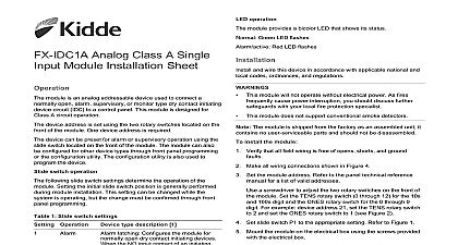
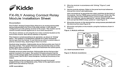
Analog Single Input Module Installation Sheet it connects 1 LED location a screwdriver to adjust the two rotary switches on the front of module Set the TENS rotary switch 0 through 12 for the 10s 100s digit and the ONES rotary switch for the 0 through 9 For example device address 21 set TENS rotary switch to 2 set the ONES rotary switch to 1 see Figure 2 Position the module into the electrical box behind the device to FX IDC1B Analog Single Input Mini Module is an analog device used to connect a normally open alarm or monitor type dry contact initiating device circuit IDC to control panel This module is designed for Class B circuit operation device address is set using the two rotary switches located on the of the module One device address is required module is factory set to operate as an alarm latching device the NO contact of an initiating device is closed an alarm signal sent to the control panel and the alarm condition is latched at the device types are available through front panel programming the configuration utility For additional information refer to the listed on the control panel label FX IDC1B provides two status LEDs The LEDs are visible from back of the module and wire this device in accordance with applicable national and codes ordinances and regulations This module does not operate without electrical power As fires cause power interruption discuss further safeguards the local fire protection specialist This module does not support conventional two wire smoke The module is shipped from the factory as an assembled unit it no user serviceable parts and should not be disassembled install the module Verify that all field wiring is free of opens shorts and ground Make all wiring connections as discussed in and shown in 3 Set the module address Refer to the panel technical reference for a list of valid addresses Red LED Alarm active Green LED Normal 2 Module address Insert screwdriver here the device as shown in Figure 3 Be sure to observe the polarity the wires to the control panel technical reference manual for wiring wiring is power limited and supervised 2020 Carrier 2 3101081 EN REV 007 ISS 19OCT20 Class A or Class B Signaling line circuit SLC in Signaling line circuit SLC out 3 Module wiring Wire nut or other listed splice or terminal block Class B 47 k EOLR Typical normally open NO initiating device maximum maximum line VDC at 350 V peak to peak fault impedance device circuit IDC resistor value resistance capacitance environment humidity temperature range k k P N EOL 47 25 per wire max max to 120 0 to 49 to 93 noncondensing at 32 to 140 to 60 information contact information see www kidde esfire com 2 3101081 EN REV 007 ISS 19OCT20