Kidde 3102226-EN R002 FX-SLC1 Single SLC Interface Card Installation Sheet
File Preview
Click below to download for free
Click below to download for free
File Data
| Name | kidde-3102226-en-r002-fx-slc1-single-slc-interface-card-installation-sheet-5132680794.pdf |
|---|---|
| Type | |
| Size | 1.37 MB |
| Downloads |
Text Preview
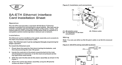
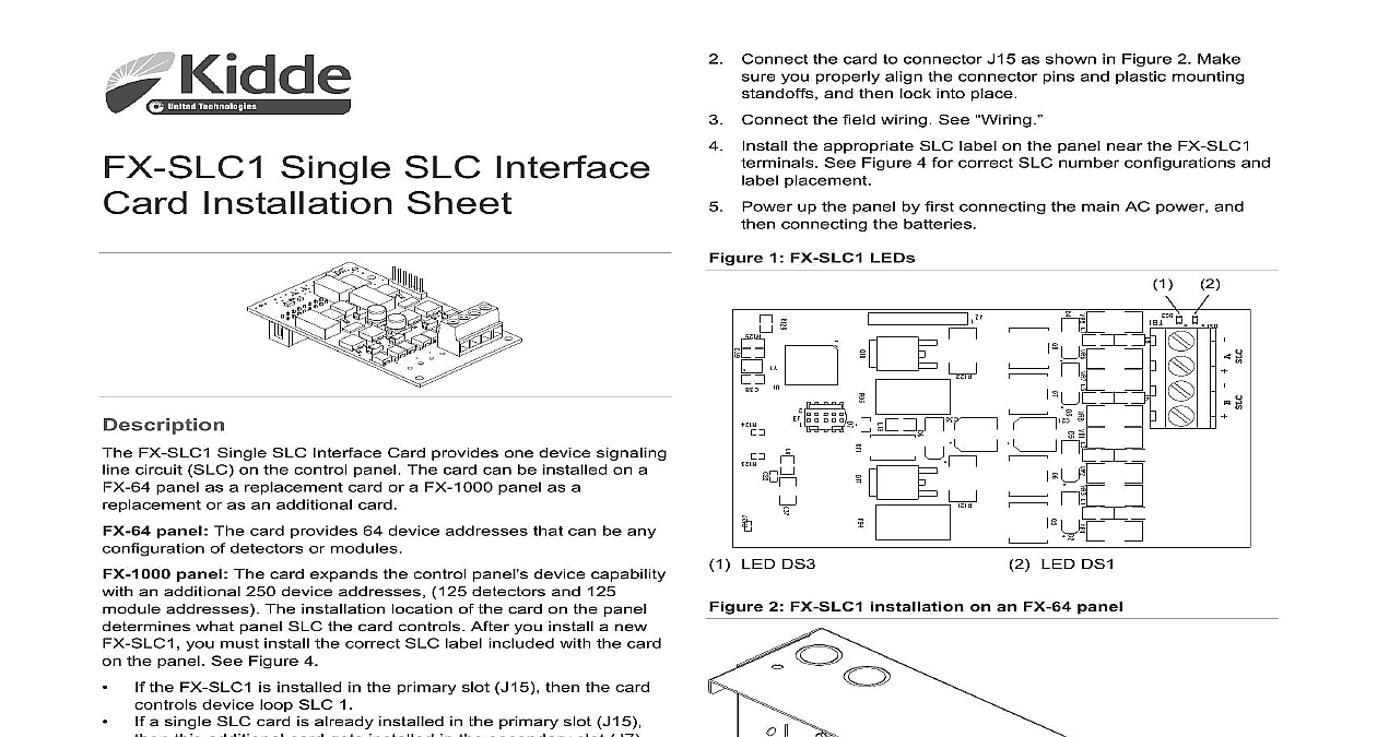
Single SLC Interface Installation Sheet Connect the card to connector J15 as shown in Figure 2 Make you properly align the connector pins and plastic mounting and then lock into place Connect the field wiring See the appropriate SLC label on the panel near the FX SLC1 See Figure 4 for correct SLC number configurations and placement Power up the panel by first connecting the main AC power and connecting the batteries 1 FX SLC1 LEDs LED DS3 2 FX SLC1 installation on an FX 64 panel LED DS1 FX SLC1 Single SLC Interface Card provides one device signaling circuit SLC on the control panel The card can be installed on a panel as a replacement card or a FX 1000 panel as a or as an additional card panel The card provides 64 device addresses that can be any of detectors or modules panel The card expands the control panel s device capability an additional 250 device addresses 125 detectors and 125 addresses The installation location of the card on the panel what panel SLC the card controls After you install a new you must install the correct SLC label included with the card the panel See Figure 4 the FX SLC1 is installed in the primary slot J15 then the card device loop SLC 1 a single SLC card is already installed in the primary slot J15 this additional card gets installed in the secondary slot J7 controls device loop SLC2 a dual SLC card is already installed in the primary slot J15 this additional card gets installed in the secondary slot J7 controls device loop SLC3 LEDs are two LEDs on the card that indicate loop communication See Table 1 and Figure 1 for location and function of the LEDs installation location of the card on the panel determines what SLC the LEDs are associated with See Figure 4 1 FX SLC1 LED functions communication Flashes to indicate normal device 1 fault Solid ON to indicate an open fault Flashes to a short fault and wire this device in accordance with applicable national and codes ordinances and regulations only one card is installed in the panel it must be installed in the position J15 Installation limits are under the jurisdiction of local authority install the FX SLC1 in a FX 64 panel Power down the panel by first disconnecting the batteries and disconnecting the main AC power Plastic mounting standoff Connector J15 FX SLC1 2017 United Technologies Corporation 3 3102226 EN REV 002 ISS 26MAR17 4 Panel SLC number configurations for FX 1000 panels install the FX SLC1 in FX 1000 panel Power down the panel by first disconnecting the batteries and disconnecting the main AC power Connect the card to connector J15 or J7 as shown in the Figure 3 sure you properly align the connector pins and plastic standoffs and then lock into place Connect the field wiring See the appropriate SLC label on the panel near the FX SLC1 See Figure 4 for correct SLC number configurations and placement Power up the panel by first connecting the main AC power and connecting the batteries 3 FX SLC1 installation on an FX 1000 panel Connector J15 primary Connector J7 secondary Panel label card provides either Class B Class A or Class X wiring options the device as shown in Figure 5 Figure 6 or Figure 7 Be sure to the polarity of the wires 5 Class B wiring Plastic mounting standoff Connector J15 primary FX SLC1 Connector J7 secondary FX SLC1 SLC device 6 Class A wiring 1 FX SLC1 SLC device 3 3102226 EN REV 002 ISS 26MAR17 7 Class X wiring 2 FX SLC1 Isolator module SLC devices SLC devices with an isolator UL ULC listed enclosure For Class X wiring un devices must be in a cabinet with on the incoming and wiring for Figure 6 and Figure 7 For Class A wiring isolator modules and isolator detector bases are to prevent wire to wire shorts on the signaling line circuit from adversely affecting other segments of the loop Do not more than 50 addressable devices between isolators per 72 For Class X wiring isolator modules and isolator detector bases are to prevent wire to wire shorts on the signaling line circuit from adversely affecting any devices of the loop addresses panel panel voltage current loaded loop line rating current total loop resistance total loop fault impedance environment humidity device addresses per loop 125 detectors and 125 addresses B Class A or Class X VDC 55 mA per loop 80 mA per loop These ratings do not include the of two wire smoke modules 20.6 V peak to peak to 18 AWG 0.75 to 2.5 mm2 A max isolators maximum per loop total both bases and modules to 5 k to 120 0 to 49 to 93 noncondensing at 90 32 information contact information see www kiddelifesafety com 3102226 EN REV 002 ISS 26MAR17 3