Kidde 3102359-EN R002 FX-T3T4 Temporal Pattern Generator Installation Sheet

File Preview
Click below to download for free
Click below to download for free
File Data
| Name | kidde-3102359-en-r002-fx-t3t4-temporal-pattern-generator-installation-sheet-9174520368.pdf |
|---|---|
| Type | |
| Size | 811.24 KB |
| Downloads |
Text Preview
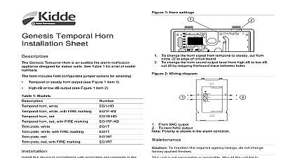
Temporal Pattern Installation Sheet FX T3T4 Temporal Pattern Generator is an addressable device to generate T3 fire or T4 CO temporal signal patterns for use compatible sounder bases The T3 and T4 temporal patterns are with NFPA 72 and NFPA 720 respectively In the United States you can use T3 or T4 In Canada you can use T3 FX T3T4 module uses two addresses on the signaling line circuit Address 1 is tied to Channel 1 which is the T3 pattern Address is tied to Channel 2 which is the T4 pattern Channel 1 always has highest priority device address is set using the two rotary switches located on the of the module Two consecutive device addresses are required second device address is automatically assigned one number than the value set on the rotary switches selection fire alarm control unit sends synchronization and channel to the FX T3T4 Channel selection determines the pattern fire alarm control unit can also send silencing commands to the system initialization the SLC controller determines which plays on each channel depending on the marketplace setting example in the US and Canadian marketplaces a fire alarm takes over a CO alarm so the T3 pattern is assigned to Channel 1 for other markets are governed by local requirements an alarm condition occurs the detector notifies the control unit the control unit commands the FX T3T4 to activate the T3T4 riser FX T3T4 generates the appropriate pattern and synchronizes all sounder bases on a single T3T4 riser The SLC controller multiple FX T3T4 modules installed on the same SLC the FX T3T4 alarm signal continues until the system resets or is manually The FX T3T4 can receive silencing commands from the panel operation FX T3T4 module uses a bicolor LED to indicate its status as Normal Green LED flashes Alarm active Red LED flashes and wire this device in accordance with applicable national and codes ordinances and regulations This module will not operate without electrical power As fires cause power interruption you should discuss further with your local fire protection specialist This module does not support conventional smoke detectors Electrical supervision requires that you break the wire run at terminal Do not loop the signaling circuit field wires around the The module is shipped from the factory as an assembled unit it no user serviceable parts and should not be Only one module is required for each T3T4 riser When determining allowable wire resistance refer to the voltage of the module the signaling appliance and the control panel Strip 1 4 in about 6 mm from the ends of all wires that connect to terminal block of the module Exposing more bare wire may a ground fault and exposing less wire may result in a faulty install the module Verify that all field wiring is free of opens shorts and ground Make the wiring connections as shown in Figure 3 Set the module address Refer to the control unit documentation a list of valid addresses a screwdriver to adjust the two rotary switches on the front of module Set the TENS rotary switch 0 through 12 for the 10s 100s digit and the ONES rotary switch for the 0 through 9 For example device address 21 set the TENS rotary switch 2 and set the ONES rotary switch to 1 see Figure 1 Mount the module on the electrical box using the screws provided the electrical box See Figure 2 on page 3 for compatible electrical boxes Mount the wall plate on the module using the hardware shown in 2 1 Module address 6 7 0 5 Insert screwdriver here 2020 Carrier 3 3102359 EN REV 002 ISS 21OCT20 2 Mounting diagram Compatible electrical box FX T3T4 6 32 1 2 screws 2X Wall plate Cover plate plastite screws 2X sounder base applications refer to the sounder base installation for details 3 Wiring Diagram Canadian installations follow CAN ULC S536 Standard for the and Testing of Fire Alarm Systems the FX T3T4 as shown in Figure 3 below For further wiring refer to FX 64 and FX 1000 Technical Reference Manual 3102352 T3T4 connects to the SIG terminal on the sounder base and connects to the SIG terminal The FX NAC is required for supervision and is ordered separately 3 Legend AUX riser from previous device Use a power limited and regulated VDC primary or auxiliary power supply that is UL ULC Listed for protective signaling systems AUX riser to the next FX T3T4 in the same notification zone or to Class A return on the power supply Signaling line circuit from previous device Compatible sounder base Signaling line circuit to next device In order to have a Class A T3T4 riser wire the SLC as Class A limit the AUX input connection to the same room within 20 ft m and enclose in conduit or equivalent protection against injury No connection Do not connect notification appliances k EOLR 6 7 0 5 9 6 7 0 5 9 3 3102359 EN REV 002 ISS 21OCT20 TC3 TC4 voltage wiring Ground fault impedance riser wiring to 33 VDC to 19.95 VDC max max to 5 k and power limited B A max Actual value limited by power outputs to 18 AWG 0.75 to 2.50 mm line circuits SLC are Style 4 B or Style 6 Class A sounder bases KI ABDT KI ABST KI ABLT electrical box environment humidity temperature in square box 1 1 2 in 38 mm deep to 120 0 to 49 to 93 noncondensing to 140 to 60 size designation rating information rating compliance 24 DC dry device complies with part 15 of the FCC Operation is subject to the following two 1 This device may not cause harmful and 2 this device must accept any received including interference that cause undesired operation Class A digital apparatus complies with ICES 003 Canada information contact information see www kidde esfire com 3102359 EN REV 002 ISS 21OCT20 3