Kidde 3102427-EN R01 Genesis Steady Horn Installation Sheet

File Preview
Click below to download for free
Click below to download for free
File Data
| Name | kidde-3102427-en-r01-genesis-steady-horn-installation-sheet-0861437529.pdf |
|---|---|
| Type | |
| Size | 647.90 KB |
| Downloads |
Text Preview
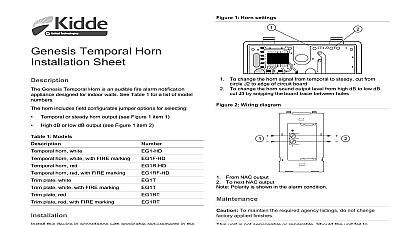
Steady Horn Sheet Genesis Horn is an audible fire alarm notification appliance for indoor walls See Table 1 for a list of model numbers in accordance with applicable requirements in the latest editions the NFPA codes and standards and Canadian Electrical Code 1 Section 32 and in accordance with the local authorities having 1 Model numbers description white white with FIRE marking red red with FIRE marking plate white plate white with FIRE marking plate red plate red with FIRE marking numbers voltage current output size electrical environment listings Table 2 Table 3 Table 4 to 22 AWG American 2 1 2 in 64 mm deep box 4 in square box 1 1 2 in 38 mm box or 4 in octagonal with EG1T or trim accessory to 120 0 to 49 to 93 RH noncondensing at 90 32 ULC S525 and UL 464 seventh edition 2 Operating voltage ULC 1 to 33 This device was tested to the regulated 24 VDC FWR operating limits of 16 V and 33 V Do not apply 80 and 110 of these for system operation to 33 3 Maximum operating current mA RMS range to 33 VDC to 33 VFWR 4 Sound output dBA 1 room per UL 464 at 16 VDC chamber per ULC S525 at 16 VDC specific SPL data in Table 5 Sound level output at 10 ft 3.05m dBA minimum dBA minimum 5 Measured SPL sound pressure levels VDC VDC VDC VFWR VFWR VFWR level output measured in an anechoic chamber per ULC S525 Volts direct current regulated and filtered Volts full wave rectified output dBA characteristics directional characteristics for the Genesis horn see the following tables 6 24 VDC horizontal axis right right left left angles are measured by moving up from on axis dB ref dB dB dB dB 7 24 VDC vertical axis up down down angles are measured from above the unit dB ref dB dB dB 2016 United Technologies Corporation 2 3102427 EN REV 01 ISS 01SEP16 information contact information see www kiddelifesafety com 8 24 VFWR horizontal axis right right left left angles are measured by moving to the right of on axis dB ref dB dB dB dB 9 24 VFWR vertical axis up down down angles are measured by moving up from on axis dB ref dB dB dB instructions The Genesis models are for indoor use only The Genesis models have no serviceable parts inside When determining allowable wire resistance refer to the voltage of the signaling device and the control panel specifications install Remove the cover by depressing both tabs on the top of the unit a small screwdriver and twisting slightly Connect wires as shown Electrical supervision requires the wire to broken at each terminal See the wiring diagram Mount on a compatible electrical box making sure not to over the mounting screws Replace the cover by aligning at the bottom then snapping in at top Test the unit for proper operation 1 Wiring diagram From NAC listed as compatible To next appliance listed end of line device or return for Class A Polarity is shown in alarm condition Refer to NAC source equipment for end of life device 2 3102427 EN REV 01 ISS 01SEP16