Kidde 3102428-EN R01 Genesis Temporal Horn Installation Sheet

File Preview
Click below to download for free
Click below to download for free
File Data
| Name | kidde-3102428-en-r01-genesis-temporal-horn-installation-sheet-0253487961.pdf |
|---|---|
| Type | |
| Size | 632.55 KB |
| Downloads |
Text Preview
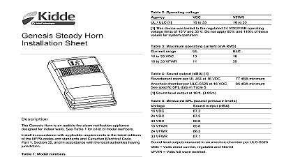
Temporal Horn Sheet Genesis Temporal Horn is an audible fire alarm notification designed for indoor walls See Table 1 for a list of model horn includes field configurable jumper options for selecting Temporal or steady horn output see Figure 1 item 1 High dB or low dB output see Figure 1 item 2 1 Models horn white horn white with FIRE marking horn red horn red with FIRE marking plate white plate white with FIRE marking plate red plate red with FIRE marking this device in accordance with applicable requirements in the editions of the NFPA codes and standards the National Building of Canada the Canadian Electrical Code Part 1 Section 32 in accordance with the local authorities having jurisdiction Electrical supervision requires breaking the wire run at each Do not loop the signaling circuit field wires around the install the horn Remove the cover by depressing both tabs on the top of the unit a small screwdriver and twisting slightly Set the horn signal and sound output level to desired settings See 1 Connect the horn terminals to the signal circuit field wiring polarity for the unit to function properly See Figure 2 Mount the unit onto a compatible electrical box making sure not to the mounting screws Replace the cover by aligning at the bottom then snapping in at top Test the unit for proper operation 1 Horn settings J3 To change the horn signal from temporal to steady cut from J2 to edge of circuit board To change the horn sound output level from high dB to low dB J3 by snipping the board trace between holes 2 Wiring diagram From NAC output To next NAC output Polarity is shown in the alarm condition To maintain the required agency listings do not change applied finishes unit is not serviceable or repairable Should the unit fail to contact the supplier for replacement a visual inspection and an operational test twice a year or as by the local authority having jurisdiction 2 Sound level output dBA and voltage 464 Sound level output at 10 ft 3.05 m measured in a room VDC VDC VDC VDC VDC VDC 3 Sound level output dBA temporal tone peak and voltage VDC VDC VDC VFWR VFWR VFWR Meets or exceeds 85 dBA in an anechoic chamber at ft 3.05 m 2016 United Technologies Corporation 2 3102428 EN REV 01 ISS 01SEP16 and compliance rating American 24 DC and 24 FWR and UL 464 information contact information see www kiddelifesafety com 4 Operating current in RMS A VDC VDC VDC VFWR VFWR VFWR Volts direct current regulated and filtered Volts full wave rectified 5 Audible directional characteristics horizontal pattern 1 Angles are measured from a perpendicular axis positive angles to right Peak output at 24 VDC set for temporal tone output dBA 2 3 6 6 Audible directional characteristics vertical pattern 1 Angles are measured from a perpendicular axis positive angles are Peak output at 24 VDC set for temporal tone output dBA 2 dBA 3 6 Voltage Operating level output directional size electrical 16 to 33 VDC 16 to 33 VFWR mA at 24 VDC Table 4 Table 2 and Table 3 Table 5 and Table 6 to 18 AWG 0.75 to 2.50 mm American 2 1 2 in 64 mm deep box 4 in square box 1 1 2 in 38 mm box 100 mm box to 120 0 to 49 to 93 noncondensing humidity environment This device was tested to the regulated 24 DC FWR operating limits of 16 V and 33 V Do not apply 80 and 110 of these for system operation 2 3102428 EN REV 01 ISS 01SEP16