Kidde 3102477-EN R001 KI-IB Detector Base Installation Sheet

File Preview
Click below to download for free
Click below to download for free
File Data
| Name | kidde-3102477-en-r001-ki-ib-detector-base-installation-sheet-9213806547.pdf |
|---|---|
| Type | |
| Size | 814.93 KB |
| Downloads |
Text Preview
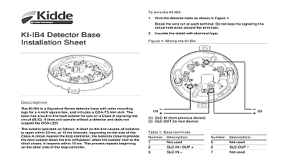
Detector Base Installation Risk of system failure Electrical supervision requires that the run be broken at each terminal Do not loop the field wires around terminals Shielded wire is required only in environments with very high noise Shields if used must be continuous and insulated from ground wire the KI IB Wire the detector base as shown in Figure 1 the wire run at each terminal Do not loop the signaling line field wires around the terminals the shield with electrical tape 1 Wiring the KI IB KI IB is a Signature Series detector base with a built in line fault for use on a Class A signaling line circuit SLC It does not without a detector and does not support the GSA LED isolator operates as follows A short on the line causes all isolators open within 23 ms at 10 ms intervals beginning on the side of the A circuit nearest the loop controller the isolators close to provide next isolator down the line with power when the isolator next to the closes it reopens within 10 ms The process repeats beginning the other side of the loop controller Risk of equipment damage To prevent damage to the base not overtighten the base mounting screws or wire terminal screws to on page 2 for torque values SLC IN from previous device SLC OUT to next device 1 Base terminals to Technical Bulletin P N 3102483 EN for location and spacing install the KI IB Mount the KI IB on a compatible electrical box using the screws with the electrical box Wire the base as shown in the section Write the address assigned to the detector on the label provided apply the label to the inside rim of the base Use a GSA TS trim skirt to finish the installation as needed Description Number Description used IN OUT IN used 5 6 7 used OUT used 2017 United Technologies Corporation 2 3102477 EN REV 001 ISS 10AUG17 resistance isolators size max to 18 AWG 1.0 to 4.0 mm 16 and 18 AWG are preferred torque mounting lbf in 2.0 N max lbf in 1.4 N max impact engineering polymer white detectors Series detectors Four Inch Box Trim Skirt Ring electrical American single gang box box 3 1 2 in 89 mm by 1 1 2 in mm deep box 4 in 102 mm by 1 1 2 in mm deep single gang box 75 mm with mm fixing centers box with 60.3 mm fixing centers environment humidity to 120 0 to 49 to 93 noncondensing bulletin 3102483 EN information contact information see www kiddelifesafety com 2 3102477 EN REV 001 ISS 10AUG17