Kidde 3102541-EN R002 RBPS Series Replacement Power Supply Board Installation Sheet
File Preview
Click below to download for free
Click below to download for free
File Data
| Name | kidde-3102541-en-r002-rbps-series-replacement-power-supply-board-installation-sheet-1329074685.pdf |
|---|---|
| Type | |
| Size | 1.10 MB |
| Downloads |
Text Preview
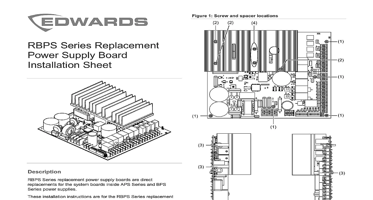
1 1 Screw and spacer locations Series Replacement Supply Board Sheet Barrel spacers 3X Do not remove 6 32 5 16 screws 5X 6 32 1 1 2 screws 3X remove the system board Power down the equipment Disconnect the field wiring Tag each wire so you can identify to connect them on the replacement system board Remove the five 6 32 5 16 screws Figure 1 item 1 and the 6 32 1 1 2 screws Figure 1 item 2 the screws and the barrel spacers aside for use later Lift the system board out of the cabinet backbox See Figure 2 Series replacement power supply boards are direct for the system boards inside APS Series and BPS power supplies installation instructions are for the RBPS Series replacement supply boards listed below board APS BPS 6 A 120 V board APS BPS 6 A 220 240 V board APS BPS 10 A 120 V board APS BPS 10 A 220 240 V the system board Electrocution hazard To avoid personal injury or death electrocution remove all sources of power and allow stored inside the cabinet to discharge before installing or removing the Equipment damage hazard This product is sensitive to discharge ESD To avoid damage follow accepted ESD procedures system board is attached to the cabinet backbox using five 5 16 screws 1 three 6 32 1 1 2 screws 2 and three spacers 3 See Figure 1 Do not remove the two screws holding the heat sink to the board See Figure 1 item 4 2020 Carrier 2 3102541 EN REV 002 REB 10DEC20 placing the unit into service placing the unit into service Set the switches and jumpers on the new system board to match old system board Attach the field wires Test the unit completely including full operation on battery power and wiring BPS Series power supplies see Remote Booster Power Supply Reference Manual P N 3100485 EN APS Series power supplies see Auxiliary Power Supply Technical Manual P N 3100970 BPS Series power supplies see Remote Booster Power Supply Reference Manual P N 3100485 EN APS Series power supplies see Auxiliary Power Supply Technical Manual P N 3100970 information contact information see www edwardsfiresafety com the system board and wire this device in accordance with applicable national and codes ordinances and regulations replacing the system board you can use the 6 32 1 1 2 and barrel spacers provided in the hardware kit or use the and spacers from the old system board Do not handle the system board in a manner that could damage components For example do not carry the system board by only one side of the heat sink or do not flex the system by placing your thumbs on the corner of the heat sink and fingers on the edge of the system board and then squeezing Do not use power tools to secure the system board to the cabinet replace the system board Carefully lift the system board out of the carton and lay it on a flat Do not bend or otherwise stress the system board as you it Place three barrel spacers between the heat sink and the system see Figure 1 item 3 and then insert a 6 32 1 1 2 screw each barrel spacer Make sure the screw goes all the way the system board Without flexing the system board carefully align it with the on the cabinet backbox See Figure 2 sure the 6 32 1 1 2 screws and barrel spacers do not fall of place Start but do not completely tighten the three 6 32 1 1 2 screws 1 item 2 1 item 1 Start but do not completely tighten the five 6 32 5 16 screws Visually inspect the barrel spacers Figure 1 item 3 to ensure that are properly in place Units will not operate properly without barrel spacers Hand tighten all eight screws 2 Removing the system board 6 32 5 16 screws 5X 2 3102541 EN REV 002 REB 10DEC20