Kidde 3102554-EN R002 Genesis LED EG4 Series Wall Notification Appliance Installation Sheet

File Preview
Click below to download for free
Click below to download for free
File Data
| Name | kidde-3102554-en-r002-genesis-led-eg4-series-wall-notification-appliance-installation-sheet-7398451260.pdf |
|---|---|
| Type | |
| Size | 2.46 MB |
| Downloads |
Text Preview
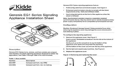
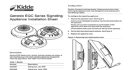
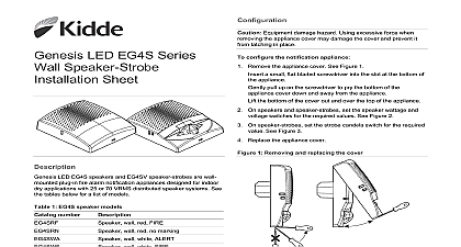
LED EG4 Series Wall Appliance Installation LED EG4 Series notification appliances feature Field configurable horn and strobe outputs See Figure 2 Enhanced synchronization circuitry to comply with the latest of UL 1638 and CAN ULC S526 wiring test points on the front of the appliance when the is removed Synchronized operation requires a separately installed device See the control unit or power supply list for compatible synchronization devices Equipment damage hazard Using excessive force when the appliance cover may damage the cover and prevent it latching in place configure the notification appliance Remove the appliance cover See Figure 1 a small flat bladed screwdriver into the slot at the bottom of appliance pull up on the screwdriver to pry the bottom of the cover down and away from the appliance the bottom of the cover out and over the top of the appliance LED EG4A horns EG4V strobes and EG4VA horn strobes wall mounted plug in fire alarm notification appliances designed for dry applications See Table 1 to Table 3 for a list of models On horns and horn strobes set the sound output switch for the value See Figure 2 On strobes and horn strobes set the light output for the required See Figure 2 Replace the appliance cover 1 Removing and replacing the cover 1 EG4A horn models number horn red FIRE horn red no marking horn white FIRE horn white no marking 2 EG4V strobe models number strobe red FIRE strobe red no marking strobe white FIRE strobe white no marking 3 EG4AV horn strobe models number horn strobe red FIRE horn strobe red no marking horn strobe white FIRE horn strobe white no marking 2020 Carrier 4 3102554 EN REV 002 ISS 31AUG20 2 Light and sound output settings 3 Typical electrical box mounting Electrical box Trim plate optional Wiring plate required Machine screw 2X supplied with wiring plate Notification appliance Shorting clip 4 Typical surface box mounting Surface box Wiring plate required Plastite screw 2X supplied with surface mount box Notification appliance Shorting clip 110 candela 75 candela 30 candela 15 candela Constant low dB Constant high dB T3 temporal low dB T3 temporal high dB Temporal 3 coding is the required output for fire notification per NFPA 72 Any device coding other than Temporal 3 is at discretion and approval of the local authority having jurisdiction and wire this device in accordance with applicable national and codes ordinances and regulations Electrical supervision requires that you break the wire run at terminal Do not loop the notification circuit field wires around the install the appliance Using the screws supplied with the wiring plate attach the wiring and if used the trim plate to the electrical box See Figure 3 Figure 4 Do not overtighten the screws trim plate is ordered separately Connect the field wiring Observe signal polarity for the appliance operate properly See Figure 4 Remove the shorting clip Figure 3 item 6 Retain for future use Plug the appliance into the wiring plate by setting the appliance on top of the wiring plate and then snapping the bottom into See Figure 5 unplug the appliance press the spring clip on the bottom and lift the appliance away from the wiring plate Test the unit for proper operation 4 3102554 EN REV 002 ISS 31AUG20 5 Wiring 7 Test points Horn strobe circuit in signal polarity shown in the active condition Horn strobe circuit out Shorting clip To maintain circuit continuity do not remove the shorting clip 4 item 3 until you are ready to install the notification 6 Removing and replacing the appliance Marking indicates signal polarity when the circuit is active voltage current signal type output pattern output flash rate distribution center electrical plate size torque Mounting screws screws plates covers environment humidity temperature to 33 VDC 16 to 33 VFWR Table 4 to Table 6 or temporal TC3 Table 7 Table 8 30 75 or 110 cd fps flash per second approx Figure 7 max between any two devices determine allowed wire resistance refer to specifications and the specifications the synchronized signal source Figure 8 in cm 2 gang 4 inch square G4RSB to 18 AWG 0.75 to 2.50 mm lbf in 1.2 N m max lbf in 1.4 N m max EG4TW Table 9 to Table 11 to 122 0 to 50 to 93 noncondensing to 158 40 to 70 and testing Equipment damage hazard To maintain the required agency do not change factory applied finishes unit is not serviceable or repairable If the unit fails to operate the supplier for a replacement a visual and operational inspection in accordance with codes and standards or as directed by the local authority jurisdiction wiring test points are available on the front of the appliance when cover is removed The test points let you easily spot check the field wiring without the need to remove the appliance from the wall Figure 6 4 Operating current horn models setting T LOW T HIGH to 33 VDC mA mA 5 Operating current strobe models setting 30 75 110 to 33 VDC mA to 33 VFWR mA mA to 33 VFWR mA 3102554 EN REV 002 ISS 31AUG20 4 6 Operating current horn strobe models 30 75 setting T LOW to 33 VDC mA T HIGH mA to 33 VFWR mA mA 7 Sound output horn and horn strobe models setting 464 dBA dBA dBA dBA T LOW T HIGH 8 Sound pattern ULC and 45 and 30 and 40 and 30 in output dBA dBA dBA dBA 9 EG4A horn replacement covers number wall horn red FIRE wall horn red no marking wall horn white ALERT wall horn white FIRE wall horn white no marking 10 EG4V strobe replacement covers number wall strobe red FIRE wall strobe red no marking wall strobe white ALERT wall strobe white FIRE wall strobe white no marking wall horn strobe red FIRE wall horn strobe red no marking wall horn strobe white ALERT wall horn strobe white FIRE wall horn strobe white no marking 11 EG4AV horn strobe replacement covers number information contact information see www kidde esfire com 8 110 cd light distribution Measured