Kidde 3102654-EN R001 SA-USB Interface Card Installation Sheet
File Preview
Click below to download for free
Click below to download for free
File Data
| Name | kidde-3102654-en-r001-sa-usb-interface-card-installation-sheet-5098714326.pdf |
|---|---|
| Type | |
| Size | 1.08 MB |
| Downloads |
Text Preview
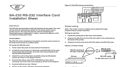
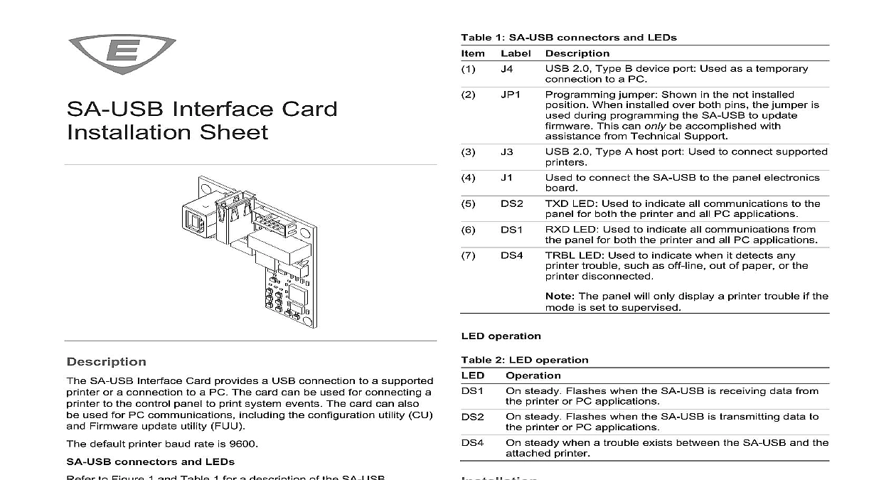
Interface Card Sheet SA USB Interface Card provides a USB connection to a supported or a connection to a PC The card can be used for connecting a to the control panel to print system events The card can also used for PC communications including the configuration utility CU Firmware update utility FUU default printer baud rate is 9600 connectors and LEDs to Figure 1 and Table 1 for a description of the SA USB 1 SA USB LEDs and connectors 1 SA USB connectors and LEDs Label Description 2.0 Type B device port Used as a temporary to a PC jumper Shown in the not installed When installed over both pins the jumper is during programming the SA USB to update This can only be accomplished with from Technical Support 2.0 Type A host port Used to connect supported to connect the SA USB to the panel electronics LED Used to indicate all communications to the for both the printer and all PC applications LED Used to indicate all communications from panel for both the printer and all PC applications LED Used to indicate when it detects any trouble such as off line out of paper or the disconnected The panel will only display a printer trouble if the is set to supervised operation 2 LED operation Operation steady Flashes when the SA USB is receiving data from printer or PC applications steady Flashes when the SA USB is transmitting data to printer or PC applications steady when a trouble exists between the SA USB and the printer and wire this device in accordance with applicable national and codes ordinances and regulations Equipment damage hazard This product is sensitive to discharge ESD To avoid damage follow accepted ESD procedures The SA USB is installed in the same location as the SA 232 the SA 232 card must be removed prior to installing the card install the SA USB Power down the panel and disconnect the batteries installed remove the SA 232 card from the panel Refer to SA RS 232 Interface Card Installation Sheet P N 3101095 for Locate the SA USB card location on the plastic assembly behind main circuit board and connector J3 on the main circuit board the top left of the main board Attach the SA USB to the plastic assembly using two 6 plastite as shown in Figure 2 Connect one end of the ribbon cable P N 7140187 to connector on the SA USB card and the other end to connector J3 on the circuit board as shown in Figure 2 Connect the applicable USB cable to the SA USB See 2021 Carrier 3 3102654 EN REV 001 ISS 12JAN21 Power up the panel and then connect the batteries 2 SA USB installation typical LCD removed for clarity installed on both pins remove jumper JP1 item 2 Figure 1 from pin on the SA USB card as shown in Figure 1 the included ferrite clamp item 3 Figure 2 onto the USB by opening and then snapping it in place over the USB cable shown in Figure 2 wiring wire to a computer Locate a powered USB 2.0 port on the computer Connect a USB 2.0 A to B cable purchased separately to the USB port J4 Figure 1 Connect the other end of the USB 2.0 cable to the SA USB card installation required driver for the SA USB will install automatically on most systems when you connect it to a computer If the driver not install automatically perform the following Make sure that the SA USB is connected to the computer and VS systems Download the SA USB driver from the My website http my eddie com to your computer FX systems Download the SA USB driver from the FX series http kiddefx kidde com to your computer Open Device Manager and then select the USB device listed Other devices Right click on the USB device and then select Update driver Select my computer for driver software and then browse the SA USB driver folder Click Next After the driver installs it is listed under Ports USB CH340 COM port will be listed as an available port in the CU and the SA USB card USB cable Ferrite clamp Ribbon cable J1 on SA USB card 6 Plastic assembly behind main circuit board J3 on the main circuit 6 plastite screw 2X wiring The printer must be enabled and configured through programming proper operation Do not install JP1 item 2 Figure 1 If jumper JP1 is installed on both pins the printer will not function The panel will display a printer trouble if the mode is set to supervised wire to a printer you have a computer connected to the SA USB card disconnect Locate the USB port on the back of the printer Refer to PT 1S Fire Printer Installation Sheet P N 3100989 for details Connect a USB 2.0 A to B cable purchased separately to the USB port voltage Serial Bus ports 1 printer cable length VDC mA max 20 mA USB Type A port J3 printer USB Type B device port J4 CU MIR PRT S supervised USB printers in the same as the equipment to which they unsupervised USB printers in the room and within 20 ft 6.1 m of the to which they connect Enclose in conduit or equivalent protection mechanical injury baud communication environment humidity to 120 0 to 49 to 93 noncondensing Connect the other end of the USB 2.0 cable to the SA USB card USB port connections are hot pluggable J3 item 3 Figure 1 3 3102654 EN REV 001 ISS 12JAN21 information compliance device complies with part 15 of the FCC Operation is subject to the following two 1 This device may not cause harmful and 2 this device must accept any received including interference that cause undesired operation Indoor dry information contact information see www edwardsfiresafety com 3102654 EN REV 001 ISS 12JAN21 3