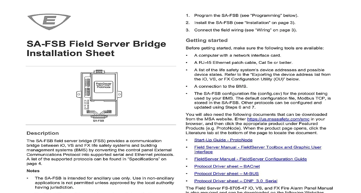
Kidde 3102662-EN R001 SA-FSB Field Server Bridge Installation Sheet

File Preview
Click below to download for free
Click below to download for free
File Data
| Name | kidde-3102662-en-r001-sa-fsb-field-server-bridge-installation-sheet-3715680492.pdf |
|---|---|
| Type | |
| Size | 1.15 MB |
| Downloads |
Text Preview
Field Server Bridge Sheet SA FSB field server bridge FSB provides a communication between iO VS and FX life safety systems and building systems BMS by converting the control panel External Protocol into supported serial and Ethernet protocols list of the supported protocols can be found in on 4 The SA FSB is intended for ancillary use only Use in non ancillary is not permitted unless approved by the local authority jurisdiction The SA FSB cannot be used for smoke control applications section describes possible SA FSB communication applications a control panel and a BMS SA FSB programming and wiring is the same for each application iO VS and FX control panels can support one SA FSB per control Each SA FSB is programmed with the point events it is for sending to the BMS of points SA FSB supports up to 3,600 programmed point events The number of programmed point events consists of the point events into the SA FSB and the point events going out to the BMS For a SA FSB you could program 1,800 point events to into the SA FSB and up to 1,800 point events to go out to your calculating the number of points in your application consider the total supported programmed point events are made up of devices smoke detector module etc and event types alarm supervisory etc and that one device point reporting into the from a panel may have many event type points going out to BMS tasks following tasks are required to prepare the SA FSB for between your control panel and a BMS 2021 Carrier 5 Program the SA FSB see below the SA FSB see on page 3 Connect the field wiring see on page 3 started getting started make sure the following tools are available A computer with a network interface card A RJ 45 Ethernet patch cable Cat 5e or better A list of the life safety system device addresses and possible states Refer to the the device address list from iO VS or FX Configuration Utility CU below A connection to the BMS The SA FSB configuration file config csv for the protocol being by your BMS The default configuration file Modbus TCP is in the SA FSB Other protocols can be configured and using Steps 6 and 7 will also need the following documents that can be downloaded the MSA website Enter https us msasafety com smc in your and then click the appropriate product under Featured e g ProtoNode When the product page opens click the tab at the bottom of the page to locate the document Start Up Guide ProtoNode Field Server Manual FieldServer Toolbox and Graphic User FieldServer Manual FieldServer Configuration Guide Protocol Driver sheet BACnet Protocol Driver sheet M BUS Protocol Driver sheet DNP 3.0 Serial Field Server FS 8705 47 iO VS and FX Fire Alarm Panel Manual also required and can be downloaded on the following Websites and VS panels My Eddie website http my eddie com panels FX series website http kiddefx kidde com the device address list from the iO VS or FX Utility CU program device addresses in the SA FSB configuration file you a list of the life safety system device addresses and possible states e g alarm trouble etc If you do not have the list you export it from the iO VS or FX Configuration Utility CU export the device address list Create a project or open an existing iO VS or FX CU project Right click the Panel menu and then click Export All System FSB Select the appropriate File Path and then click Export to export the file data to the computer By default the file is Name Panel Name All System Events csv field baud rate is fixed at 9600 Node ID and protocol can be set in configuration file refer to Step 6 1 Download and install the FieldServer Toolbox Enter https us msasafety com smc in your browser and then click under Featured Products When the product page under Additional Resources click Software Downloads FieldServer Toolbox 3102662 EN REV 001 ISS 23FEB21 Unzip the file and then double click the FieldServer Toolbox file to install the toolbox The toolbox will be used to a diagnostic log to help debug programming 2 Power up the SA FSB Ensure that the Frame GND FG terminal is used to ground the connection See on page 3 Connect power wiring from the SA FSB power terminals on the connector to a control panel constant 24VDC power COM and or other 24 VDC power source See 5 3 Confirm SA FSB connectivity and connect to the GUI Connect one end of the Ethernet network cable to the Ethernet jack the SA FSB and the other end to the jack on the PC Confirm connectivity as instructed in the Start Up Guide The default IP address of the ProtoNode is the subnet mask is 255.255.255.0 4 Change the SA FSB IP Settings Open your internet browser Chrome and enter the IP address of SA FSB Default is 192.168.1.24 Expand the setup folder under navigation tree and then click Settings Enter the IP address subnet mask Gateway as per the existing configuration sure that your computer IPv4 address is on the same as the SA FSB Click System Restart to update the configuration file in the 5 Loading the All System Events csv file on the SA FSB Open your Internet browser chrome and enter IP address of Expand the Setup folder under Navigation Tree and then click File select General tab All System Events csv file from the saved location Choose the file and select the Submit button 6 Download the protocol configuration system point events can be relayed to the BMS by device addresses in the SA FSB configuration file Enter the below URL on your browser chrome with the configured address Ex 192.168.1.24 iovsfx html The IOVSFX FACP configuration page opens as shown in 1 1 IOVSFX FACP configuration page Select the language as per the iO VS or FX CU configuration Enter the Max loops connected as per your project configuration English 4 loops Enter the Max devices per loop and VS panels 250 devices FX panel 325 devices Select the desired BMS protocol e g Bacnet IP is no support for specific event state preference only Multi MI and Binary State BI are supported for DNP3 Enter the Max zone depending on the panel 16 for 64 point panels 32 for 1,000 point panels Select the appropriate option s for receiving the type and category events that you want BMS to receive you have specific preferences carefully select all the desired types and categories Multiple options can be selected Serve Off Normal Binary Bi objects to BMS set this to 1 if you want binary states and not the exact event type Serve System Event data to BMS set this to 1 if you want events sent to BMS Serve Annun data to BMS set this to 1 if you want annunciator events sent to BMS Serve Zone data to BMS set this to 1 if you want zone related sent to BMS Serve Alarms only set this to 1 if you want alarm events sent BMS Serve Supervisory only set this to 1 if you want supervisory sent to BMS Serve Troubles only set this to 1 if you want trouble events to BMS BMS Serve Monitor only set this to 1 if you want monitor events sent For all BMS protocols except BACnet IP MSTP click Generate and new configuration using default labels For BACnet IP MSTP there are no label preferences click on Generate and use configuration using default labels there are label preferences go to Import Labels from FACP Click Choose File and select the All S


