Kidde 3102677-EN R001 KIR-OSHD Instllation Sheet

File Preview
Click below to download for free
Click below to download for free
File Data
| Name | kidde-3102677-en-r001-kir-oshd-instllation-sheet-1256038974.pdf |
|---|---|
| Type | |
| Size | 975.35 KB |
| Downloads |
Text Preview
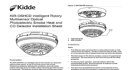
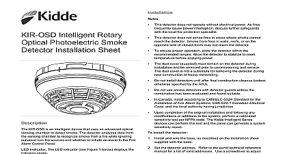
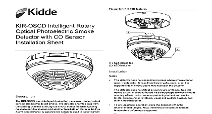
Intelligent Rotary Optical Smoke and Heat Installation Sheet KIR OSHD is an intelligent device that contains an optical smoke and a rate of rise heat sensor with a fixed temperature setting detector analyzes data from both the heat sensor and optical chamber to recognize smoke from a fire while ignoring non fire sources and whether to initiate an alarm to the Fire Control Panel This device can be operated as a single detector smoke or heat to initiate an alarm or as a split sensor with heat smoke initiating separate signals indicator The LED indicator see Figure 1 below displays the states Normal Green LED indicator flashes no action Alarm active Red LED indicator flashes evacuate the area 1 KIR OSHD features Self locking tab LED indicator and wire this device in accordance with applicable national and codes ordinances and regulations studies indicate that heat detectors should only be when property protection alone is involved The heat sensor this device provides a source of supplemental information The sensor by itself does not provide life safety protection Never on heat detectors as the sole means of fire protection This detector does not operate without electrical power As fires cause power interruption discuss further safeguards the local fire protection specialist This detector does not sense fires in areas where smoke or heat reach the detector Smoke or heat from fires in walls roofs on the opposite side of closed doors may not reach the detector To ensure proper operation store the detector within the ranges Allow the detector to stabilize to room before applying power The dust cover supplied must remain on the detector during and be removed prior to commissioning and service dust cover is not a substitute for removing the detector during construction or heavy remodeling Do not install detectors until after final construction cleanup unless specified by the AHJ Do not use smoke detectors with detector guards unless the has been evaluated and found suitable Canada install according to the CAN ULC S524 Standard for Installation of Fire Alarm Systems the CSA C22.1 Canadian Code and the local authority having jurisdiction Upon completion of the original installation and following any or additions to the system perform a calibrated test per NFPA code The Kidde Intelligent Series can perform this test and the panel can generate a system report install the detector and wire the base as described on the installation sheet with the base Set the detector address Refer to the panel technical reference for a list of valid addresses Use a screwdriver to adjust two rotary switches on the back of the detector Figure 1 Set the left rotary switch 0 through 12 for the 10s 100s digit and the right rotary switch for the 0 through 9 digit Attach the detector to the base by rotating the detector clockwise it snaps into the locked position 2020 Carrier 2 3102677 EN REV 001 ISS 02DEC20 1 Setting detector address address 52 shown 6 7 8 5 Insert a screwdriver here to set the address testing notify the proper authorities that the fire alarm system is maintenance and will be temporarily out of service each sensor in the detector Heat damage Excessive heat may damage the detector cover Do not apply excessive heat when using a hair dryer using a Testifire detector tester you must install a SIGA Testifire Assembly sure the SIGA Testifire Adapter Assembly model is installed in the Testifire detector tester before Refer to the SIGA Testifire Adapter Assembly Installation P N 3101942 ML for further details perform an initial installation test Remove the detector from its base and verify that the proper address trouble signals and messages are reported For KIR OSHD detectors placed in the air ducts verify that the is within specifications See below wired for Class A operation verify that the detector continues to first with SLC IN disconnected and then with SLC OUT Refer to the installation sheet for the base Place a momentary ground fault on the SLC circuit to verify of the ground fault detection circuitry Run a system detector sensitivity report on all detectors and verify readings fall within acceptable limits Perform a sensor function test as described below perform sensor function tests desired use the fire alarm control panel to put the detector or into a service group for testing Refer to the panel technical manual for instructions Activate the smoke sensor using No Climb Products model Smoke FireTech Smoke or Smoke Sabre smoke aerosol a smoke generator or the Testifire detector tester per the instructions Activate the heat sensor using a hair dryer maintaining a distance three inches or using a Testifire detector tester per the instructions ensure proper operation plan maintenance regular or selected of detector in accordance with the AHJ and all applicable governing codes or standards Refer to CAN ULC S536 Standard for the and Testing of Fire Alarm Systems and NFPA 72 National Alarm and Signaling Code to Technical Bulletin P N 3102650 EN for additional information cleaning instructions voltage level operating current to 19.95 VDC uA uA to 35 Hz with an amplitude of in to 4,000 ft min 0 to 20.32 m s 8 ft 15.2 m centers in 305 mm max velocity 1 spacing Heat Detectors 2 mount distance from bases KI SB4 KI RB4 KI IB4 KI ABLT KI ABST detector testers 3 Testifire 1000 Testifire 2000 environment humidity temperature compensation For duct installation use a KI DMP duct detector mounting plate install per P N 3102482 EN When replacing KI HFD and KI HRD detectors with the KIR OSHD that the spacing is 50 ft 15.2 m or less Requires the SIGA2 TSTSPACER Testifire adapter assembly to 100 0 to 38 to 93 noncondensing to 140 to 60 CAN ULC S530 UL 268 7 268A UL 521 to 4.36 ft 1.63 to 13.62 m obscuration information American smoke range fixed alarm Actual point compliance 57.2 to 141 53.9 to 60.6 device complies with part 15 of the FCC Operation is subject to the following two 1 This device may not cause harmful and 2 this device must accept any received including interference that cause undesired operation Class A digital apparatus complies with ICES 003 Canada information contact information see www kidde esfire com 2 3102677 EN REV 001 ISS 02DEC20