Kidde 3102678-EN R001 KIR-OSHCD Installation Sheet
File Preview
Click below to download for free
Click below to download for free
File Data
| Name | kidde-3102678-en-r001-kir-oshcd-installation-sheet-2630457819.pdf |
|---|---|
| Type | |
| Size | 1000.95 KB |
| Downloads |
Text Preview
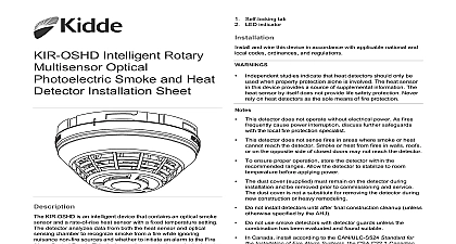
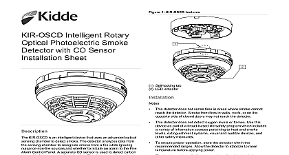
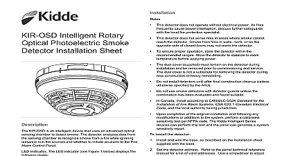
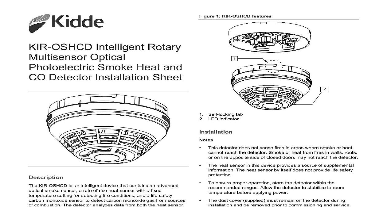
1 KIR OSHCD features Intelligent Rotary Optical Smoke Heat and Detector Installation Sheet KIR OSHCD is an intelligent device that contains an advanced smoke sensor a rate of rise heat sensor with a fixed setting for detecting fire conditions and a life safety monoxide sensor to detect carbon monoxide gas from sources combustion The detector analyzes data from both the heat sensor the optical sensing chamber to recognize smoke from a fire while nuisance non fire sources and whether to initiate an alarm to Fire Alarm Control Panel The detector analyzes the smoke and sensors independently from the CO sensor to determine whether initiate a fire alarm a life safety CO alarm or both indicator The LED indicator see Figure 1 displays the following Normal Green LED indicator flashes no action Alarm active Red LED indicator flashes evacuate the area end of life indicator The detector signals a ACT condition on the control panel when the CO sensor its end of life Pressing the Details button on the control panel OF LIFE ACT providing verification that it is an end of trouble of the CO sensor This trouble remains active until the is replaced even if the panel is reset Self locking tab LED indicator This detector does not sense fires in areas where smoke or heat reach the detector Smoke or heat from fires in walls roofs on the opposite side of closed doors may not reach the detector The heat sensor in this device provides a source of supplemental The heat sensor by itself does not provide life safety To ensure proper operation store the detector within the ranges Allow the detector to stabilize to room before applying power The dust cover supplied must remain on the detector during and be removed prior to commissioning and service dust cover is not a substitute for removing the detector during construction or heavy remodeling Do not install detectors until after final construction cleanup unless specified by the AHJ Do not use smoke detectors with detector guards unless the has been evaluated and found suitable per NFPA 72 National Fire Alarm and Signaling Code 720 Standard for the Installation of Carbon Monoxide CO and Warning Equipment and UL 2075 Standard for Gas Vapor Detectors and Sensors Upon completion of the original installation and following any or additions to the system perform a calibrated test per NFPA code The Kidde Intelligent Series can perform this test and generate a system sensitivity install the detector and wire the base as described on the installation sheet with the base Set the detector address Refer to the panel technical reference for a list of valid addresses Use a screwdriver to adjust two rotary switches on the back of the detector Figure 1 Set the left rotary switch 0 through 12 for the 10s 100s digit and the right rotary switch for the 0 through 9 digit Attach the detector to the base by rotating the detector clockwise it snaps into the locked position 2020 Carrier 4 3102678 EN REV 001 ISS 02DEC20 required by the AHJ or local codes affix the supplied CO Label P N 3303928 in proximity to the detector 1 Setting detector address address 52 shown 6 7 8 5 Insert a screwdriver here to set the address monoxide alarm procedure The carbon monoxide CO alarm indicates the presence CO which can kill you If the alarm signal sounds four times pauses five seconds and then repeats the pattern follow the steps shown Move to fresh air immediately outdoors or by an open door or Check that all persons are accounted for Do not reenter premises or move away from the open door or window until services responders have arrived the premises have aired out and your detector remains in normal condition Call emergency services the fire department or 911 about carbon monoxide Read these installation instructions in their entirety before Leave these instructions with the owner user of this detection equipment This product is intended for use in indoor locations of dwelling It is not designed to comply with Occupational Safety and Administration OSHA commercial or industrial standards The detector only indicates the presence of CO gas at the Carbon monoxide gas may be present in other areas Failure to properly install test and maintain a CO detector may it to fail potentially resulting in loss of life of this detector is not a substitute for proper installation and maintenance of fossil fuel burning appliances including ventilation and exhaust systems To reduce the risk of CO poisoning test the detector operation not in use for 10 days or more This detector does not operate without electrical power As fires cause power interruption discuss further safeguards the authority having jurisdiction AHJ Do not paint the detector Regulatory code may require that the system generate a three temporal code TC3 for fire alarms and a four pulse code TC4 for CO alarms The CO sensor is calibrated at the factory CO sensitivity is set to to UL 2034 requirements and cannot be changed by the See information on page 4 for specific values Connect this detector only to a UL Listed control panel capable of between alarm signals fire burglary CO etc and distinct identification for each To reduce the likelihood of nuisance alarms ventilate spaces when using household cleaning supplies similar contaminants If a detector has been exposed to such test it promptly afterwards of CO poisoning following symptoms related to CO poisoning should be discussed all occupants of the protected site exposure Slight headache nausea vomiting fatigue runny nose eyes often described as symptoms exposure Severe throbbing headache dizziness drowsiness fast heart rate exposure Unconsciousness brain damage convulsions failure death cases of reported CO poisoning indicate that while victims are they are not well they become so disoriented that they are to save themselves by either exiting the building or calling for Young children and pets may be the first affected sources CO sensor in this detector is designed to detect carbon monoxide from any source of combustion It is not intended to detect fire or any other gas Potential CO sources include fuel fired e g space heater furnace water heater range oven dryer other sources of combustion e g kerosene burning or heater or gas log fireplace or internal combustion engines addition excessive exhaust spillage or reverse venting of fuel appliances can produce dangerous transient levels of CO can be caused by external conditions Wind direction velocity or a combination of both including high of wind or insufficient draft in vent pipes Temperature inversions that can trap exhaust gases near the Negative pressure differential resulting from the use of exhaust Simultaneous operation of several fuel burning appliances for limited internal air Vent pipe connections vibrating loose from dryers furnaces or heaters Obstructions in vent pipes or unconventional vent pipe designs can amplify the above situations Poorly designed or maintained chimneys and or vents Extended operation of unvented fossil fuel burning devices range fireplace etc cars in an open or closed attached garage or near the limitations of CO detectors detector is designed to protect individuals from the acute affects CO exposure It will