Kidde K85001-0341 -- Temporal Horns and Horn-strobes

File Preview
Click below to download for free
Click below to download for free
File Data
| Name | kidde-k85001-0341-temporal-horns-and-horn-strobes-1406593728.pdf |
|---|---|
| Type | |
| Size | 937.97 KB |
| Downloads |
Text Preview
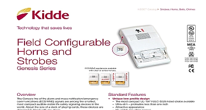
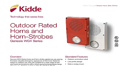
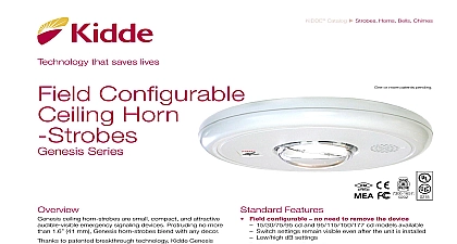
Temporal Horns Horn strobes Series temporal horns and temporal horn strobes are specially for use with compatible life safety communication and equipment to alert occupants of a life safety event The emits a piercing low frequency sound that is easily heard moderate ambient noise levels The flash from its strobe be noticed from almost any position in the room corridor or open space rugged plastic housing is made from durable and fire high impact plastic with a slightly textured surface Its mounting plate firmly holds the device in place with a screw A separate trim plate is not required Terminals ac up to 12 AWG 2.5mm wire for polarized connections are shipped with standard wall mount style lens Where ceiling orientation other languages or different markings are required LKW and LKC series Lens Marking are also available These optional lens markings simply snap to the strobe horns and horn strobes are designed for 16 to 33 Vdc and must be connected to signal circuits that output a not pulsed voltage A diode is used to allow full signal supervision Features UL 1971 listed synchronizing strobe strobes synchronize to the latest UL 1971 require when used with a synchronization source Adjustable Audible Output temporal or continuous tones and High setting for 98 output or Low setting for 94 dBA sound output Genesis compatible Genesis and Integrity strobes on the same circuit meet UL synchronization requirements when used with an external module Approved for public and private mode applications 1971 listed as signaling devices for the hearing impaired UL 1638 listed as protective visual signaling appliances Durable red or white Noryl front plate for outdoor industrial or harsh environments Field changeable field markings language or standard marking is easily changed optional LKW and LKC series lens kits Easy Installation mount to standard North American 4 square or two box Integrity universal mounting plate allows it to be and then left hanging free for easy inspection and testing it is fastened to the electrical box 1 of 6 D A T A S H E E T K85001 0341 to be used for installation purposes Issue 1.1 Catalog u Strobes Horns Bells Chimes03 31 20Technology that saves livesfirealarmresources com The installation of visible and audible signals are subject to national and local standards codes and ordinances your Authority Having Jurisdiction for device installation requirements application standards and minimum performance specifications installation the horn is configured for steady or temporal signal and either low 94 dBA or high 98 dBA output When output is selected all horns on a common two wire are self synchronized see specifications External control are not required for audible synchronization sound pressure level for each signaling zone used with or alarm signals is at least 15dB above the average ambi sound level or 5dB above the maximum sound level having a of at least 60 seconds whichever is greater measured 1.5m above the floor The average ambient sound level is the A weighted sound pressure measured over a 24 hour period the distance from the signal to the ear will theoretically result a 6 dB reduction of the received sound pressure level The actual depends on the acoustic properties of materials in the space A 3 difference represents a barely noticeable change in volume are UL 1971 listed for use indoors as wall mounted public notification appliances for the hearing impaired Prevailing require strobes to be used where ambient noise conditions specified levels where occupants use hearing protection in areas of public accommodation Consult with your Authority Jurisdiction for details part of the Enhanced Integrity line of products INT Series exceed UL synchronization requirements within 10 mil other over a two hour period when used with a syn source Synchronization is important in order to avoid sensitivity strobes are fully compatible with Genesis Series signals The flash intensity of some visible signals may not be adequate alert or waken occupants in the protected area Research indicates the intensity of strobe needed to awaken 90 of sleeping persons is 100 cd Kidde recommends that strobes in sleeping rooms rated at at least 110 cd These devices will not operate without electrical power As frequently cause power interruptions further safeguards such as power supplies may be required Sound Output Distribution measured at 10 ft in anechoic chamber Series Temporal Horn output and models fit to a standard flush North American two electrical box 2 inch 69 minimum Optional flush are not required For sur mount use Kidde custom and outdoor surface boxes in color matched red or epoxy Kidde recommends fire alarm horn strobes always installed in accordance with latest recognized edition of and local fire alarm codes 2 of 6 D A T A S H E E T K85001 0341 to be used for installation purposes Issue 1.1 Wiring strobe must be connected to signal circuits which output constant not pulsed voltage The horn can be connected to voltage circuits Operating Current RMS Vdc Vfwr cd cd cd cd cd Vdc Vfwr cd cd cd cd cd Volts direct current regulated and filtered Volts full wave rectified Draw Notes and Comments Current values are shown in mA UL Nameplate Rating can vary from Typical Current due to measurement meth and instruments used Kidde recommends using the Typical Current for system design including NAC Power Supply loading and voltage drop calculations Use the 16 Vdc RMS current ratings for filtered power supply and battery AH Use the 16 Vfwr RMS current ratings for unfiltered power supply Fuses circuit breakers and other overcurrent protection devices are typically for current in RMS values Most of these devices operate based upon heating affect of the current flowing through the device The RMS current Output dB Output dB Output dB Output dB Output anechoic anechoic anechoic anechoic the heating affect and therefore the trip and hold threshold for those Output Notes and Comments All values shown are dBA measured at 10 feet 3.01m UL1480 values measured in reverberation room Average values are measured in anechoic chamber 3 of 6 D A T A S H E E T K85001 0341 to be used for installation purposes Issue 1.1 Output Patterns cd 5A Series Strobes cd 7A Series Strobes cd 3A Series Strobes cd 4A Series Strobes cd 8A Series Strobes Output e grees Output e grees Output e grees Output e grees Output e grees 20 10 20 30 100 Output Output Output Output Output