Kidde K85001-0560 -- Reflective Beam Detector

File Preview
Click below to download for free
Click below to download for free
File Data
| Name | kidde-k85001-0560-reflective-beam-detector-4501897632.pdf |
|---|---|
| Type | |
| Size | 1.04 MB |
| Downloads |
Text Preview
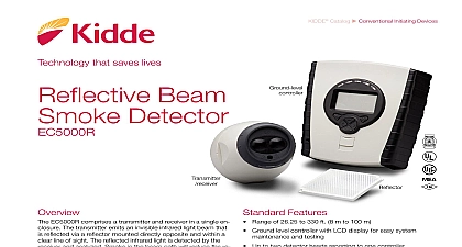
Reflective Beam Detector Smoke EC 50R 100R comprises a transmitter and receiver in a enclosure and is usually installed between 19 inches and inches below the ceiling The transmitter emits an invisible light beam that is reflected via a prism mounted directly and with a clear line of sight The reflected infrared light detected by the receiver and analyzed Smoke in the beam path reduce the received infrared light proportionally to the density the smoke The detector analyzes this attenuation or obscura of light and acts accordingly Detectors are typically mounted feet 9.14 m of a potential fire source Consult your Having Jurisdiction for spacing requirements specific to locality Features Coverage 50R range 15 160 ft 4.6 48.8 m range 160 330 ft 48.8 100 m Microprocessor controlled Automatic drift compensation Simple alignment Selectable alarm thresholds 24 Vdc operating voltage Latching or non latching operation Low current consumption Optional Ground Level Test Station Station Threshold Alarm thresholds of 25 35 and 50 can be selected to suit the environment with 25 most sensitive setting The factory default setting is 35 percent is used for most typical applications If the received infrared reduces to below the selected threshold for approximately seconds the fire relay is activated Alarm There are two modes to the operation of the fire Auto reset mode will reset the fire relay 5 seconds after the infrared signal has recovered to a level above the Alarm Latching mode holds the fire relay active indefinitely an Alarm condition has occurred To clear the latched mode must be removed from the Detector for a minimum of 5 Alarm If the infrared beam is obscured rapidly to a level 90 or greater for approximately 10 seconds the Trouble relay activated Typical causes of trouble include an object being in the beam path transmitter failure loss of the prism or misalignment of the detector The Trouble relay will reset 2 seconds of the trouble being cleared Gain Control AGC The Detector monitors long degradation of signal strength caused by component aging build up of dirt on optical surfaces By comparing the received signal against a standard every 15 minutes the detec automatically compensates for signal differences of less than When the detector is showing AGC fault detector is capable of generating an alarm and will display both Alarm Trouble indications 1 of 4 D A T A S H E E T K85001 0560 to be used for installation purposes Issue 1.1 Catalog u Conventional Initiating03 31 20Technology that saves livesfirealarmresources com Stations optional Ground Level Test Station facilitates testing of a connect detector from safe and convenient location The unit is key oper with a two position Test Run switch and includes two dedicated one for Alarm indication and one for Power indication the test station key is inserted and turned to the Test the Power LED flashes to indicate that power is con and that the 2 wire data link cable is correctly installed several seconds in the test position the test station initiates alarm at the detector head which is indicated by the red on the detector and the Alarm LED on the test station Test automatically times out after 20 seconds at which time the returns to standby mode regardless of the test station position between the test station and the detector is made means of a 2 wire data link cable The test station requires a 30 Vdc power connection Filter A test filter is supplied with the detector which is used verify the alarm threshold See the installation sheet for details testing and calibration beam smoke detectors are ideal for large open areas as warehouses hotel atriums industrial plants and school infrared signal is projected out of the transmitter optics to the placed at the opposite end of the detection zone The is reflected back to the receiver where it is analyzed for fire trouble The EC 50R 100R must be positioned correctly to the detection time The maximum lateral distance either of the beam is found to be typically 30 feet 9.1 m for satis detection under flat ceilings providing a total area cover of 19,800 square feet 60 feet x 330 feet or 1844 square 18.3 x 100.6 m stratification may be overcome by mounting multiple beam at different heights one of which will project an infrared below the heat layer and into the smoke layer time will be longer in a building with a peaked roof if a occurs at the fringes of the protected area If in doubt conduct smoke tests Spacing Detector to 24 inches to 610 mm ideal location and spacing of the Detector is critical in a prop installed and operating fire alarm system It is recommended the detectors be located and spaced in accordance with the Fire Protection Association NFPA Standard 72 The Fire Code No liability will be accepted for applications conforming to NFPA regulations recommended installation height is approximately 19 to 24 483 to 610 mm below the ceiling However in all instal the National Fire Standards for that country state must be of the reflecting properties of the beam all objects must kept a minimum of 19 inches 483 mm away from the centre the beam path down the entire beam length If highly reflective are close to the beam then greater clearances should be Positioning the reflector s on a secure surface directly opposite the Ensure that there is a clear line of sight between the and the reflector s and that no moving objects such as or mechanical equipment interfere with the beam path All should be kept a minimum of 19 inches 483 mm away the center of the detector beam down the entire length of the path Reflectors should not be mounted on glass or reflec surfaces 102 mm mm detectors should be mounted between and 160 feet 4.6 and 48.8m from a single detectors should be between 160 and 330 feet and 100.6 m from a group of reflectors mm 204 mm mm mm mm mm mm mm mm mm of four reflectors Detectors ft 18.3 m max positioning shown here is recommended for protected with flat ceilings Spacing may vary for areas with high or ceilings In such cases verify operation with smoke tests in to 30 ft Ft max in to 30 ft mm to 9.14 m m mm to 9.14 m some cases potential smoke layering may be overcome by multiple beam detectors at different heights 2 of 4 D A T A S H E E T K85001 0560 to be used for installation purposes Issue 1.1 Level Test Station 69.85 mm 38.1 mm Wiring field wiring interface is accessed through the back plate of the head The 8 pin connector is the interface to the field and numbered left to right This diagram is an example for a single beam unit installed as the only device on a zone The operation for Fire and Trouble should always be verified are shown in quiescent standby condition Alarm and of Line resistor values are determined by the fire alarm control and market standard practices Wiring to 30 Volts DC RED BLACK Relay Relay YELLOW BLUE WHITE GREEN Wiring Resistor required for American Markets of Line Resistor JB EC 100R ASSY 3 FT Installation the detector to a secure surface not subject to movement or Use the template provided to mark and install four fixing Secur


