Kidde K85001-0667 -- Genesis LED EG1 Series Compact Notification Devices

File Preview
Click below to download for free
Click below to download for free
File Data
| Name | kidde-k85001-0667-genesis-led-eg1-series-compact-notification-devices-1026489573.pdf |
|---|---|
| Type | |
| Size | 1.96 MB |
| Downloads |
Text Preview
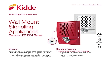
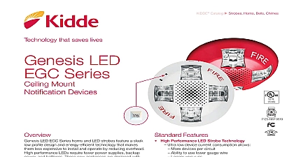
Genesis LED Series Notification Devices LED EG1 Series horns and LED strobes feature a sleek profile design and energy efficient technology that makes less expensive to install and operate by reducing overhead performance LEDs require fewer circuits and power supplies new appliances are designed with energy efficiency and life in mind LED EG1 Series uses high efficiency optics combined patented electronics to deliver a highly controlled and focused light distribution pattern in exchange for lower requirements Strobes feature field selectable 15 30 75 cd light output with Xenon type strobes Genesis LED EG1 Series need fewer power supplies and often smaller wire which lightens conduit requirements They are also compatible with legacy strobes so there no need replace all your existing devices to upgrade to new LED In fact EG1 strobes can be mixed on the same circuit used in the same field of view as Xenon based strobes This Genesis LED EG1 Series ideal for new installations and alike sound output levels provide the flexibility life safety projects demand while the Genesis LED protocol keeps multiple strobes on compatible NAC synchronized to well within NFPA 72 requirements is another area where EG1 Series appliances shine innovative under cover diagnostic test points provide easy to device circuit testing while mounted Features High Performance LED Strobe Technology Ultra low device current consumption High efficiency optics Selectable 15 30 or 75 cd light output LED devices may be mixed with legacy Xenon strobes Efficient Audible Output Selectable high or low dB horn output Selectable temporal or steady horn output Improved audio frequency range for better wall penetration Low profile Design Compact design gang mounting Ultra slim about 1 from the mounting surface Attractive appearance visible mounting screws Multiple Cover Options Order with FIRE markings or no FIRE markings in both red and white Change markings at any time with quick swap covers Easy to Install Diagnostic test points streamline device circuit testing Fits standard 1 gang electrical boxes no trim ring needed Optional trim ring available for 4 inch square boxes Slide switches for field configuration 12 to 18 AWG in out screw terminals for quick wiring 1 of 6 D A T A S H E E T K85001 0667 to be used for installation purposes Issue 1.2 Catalog u Strobes Horns Bells ChimesTechnology that saves livesfirealarmresources com LED EG1 Series strobes are UL 1971 listed for use as wall mounted public mode notification appliances the hearing impaired Prevailing codes require strobes to be where ambient noise conditions exceed 105 dBA 87 dBA Canada where occupants use hearing protection and in of public accommodation as defined in the Americans Disabilities Act is important in order to avoid epileptic sensitivity Genesis LED strobes exceed UL synchronization requirements 10 milliseconds over a two hour period when used with synchronization source See the specifications table for a list compatible sources LED horn output reaches as high as 92 dBA and features improved audio frequency range compared with other Genesis horns This results in excellent sound penetration through and a clear warning of danger They can also be set for high low dBA output This setting reduces horn output by about 6 Horn only models may be ceiling mounted or wall mounted may be configured for either coded or non coded notification circuits suggested sound pressure level for each signaling zone used alarm signals is at least 15 dBA above the average ambient level or 5 dBA above the maximum sound level having a of at least 60 seconds whichever is greater These values measured at five feet 1.5 m above the floor The average sound level is A weighted fast response sound pressure over a 24 hour period the distance from the signal to the ear will theoretically in a 6 dBA reduction of the received sound pressure level actual effect depends on the acoustic properties of materials the space A 3 dBA difference represents a barely noticeable in volume Genesis LED devices come with mounting screws for easy The tab at the bottom of the device unlocks the cover reveal the mounting holes The shallow depth of Genesis LED leaves ample room behind them for extra wiring Once with the cover in place no mounting screws are visible in LED EG1 Series horns and strobes mount to any one gang surface or flush electrical box Matching EG1T trim rings are available to cover oversized openings can accommodate one gang or four inch square boxes color matched single gang surface boxes are also Box Ring Backplate Appliance Cover Box Octagon Box Square Box Ring a trim ring is optional when installing the appliance on electrical greater than three inches out polarity shown in the active condition 2 of 6 D A T A S H E E T K85001 0667 to be used for installation purposes Issue 1.2 Notification Appliances cm cm Trim Ring cm cm Configuration horn and horn strobe models are factory set to sound a three pulse temporal pattern By sliding the tone selector units may be configured for constant horn output that be coded at precise intervals by KIDDE control panels and modules Temporal 3 coding is the required output for fire notification per NFPA 72 Any device coding other than temporal is at the discretion and approval of the local authority having AHJ cm and horn strobes are factory set for high dB output Low output may be selected by sliding the tone selector switch reduces the output by about 6 dBA LED clear strobes and horn strobes may be set for 15 or 75 candela output The output setting is changed by simply the cover and sliding the candela switch to the desired The device does not have to be removed from the wall change the output setting The setting remains visible through small window on the left hand side of the device after the cover closed temporal horn high dB temporal horn low dB horn high dB horn low dB cm candela candela candela 30 75 to 33 mA to 33 mA current to 33 to 33 mA mA mA mA 30 75 setting to 33 VDC to 33 VFWR T Low T High mA mA mA mA points indicated above are used to validate the Notification Circuit and verify device function 3 of 6 D A T A S H E E T K85001 0667 to be used for installation purposes Issue 1.2 464 S525 Left 20 15 10 5 10 15 20 25 Right Output Distribution setting dBA dBA and 115 and 130 and 135 and 140 dBA dBA dBA dBA dBA dBA pattern ULC in output Bottom Minumum voltage signal type output flash rate sources size W offset electrical boxes 1 rings Listings environment Temperature Relative humidity to 33 VD