Kidde K85010-0157 -- VS Communications Bridge

File Preview
Click below to download for free
Click below to download for free
File Data
| Name | kidde-k85010-0157-vs-communications-bridge-3196540827.pdf |
|---|---|
| Type | |
| Size | 1.00 MB |
| Downloads |
Text Preview
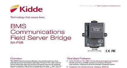
BMS Server Bridge Bridge BMS Communication Bridges are ancillary devices that protocol translation between VS1 or VS4 control panel data and the se rial or Ethernet input of an external device Signal flow is typically one way from the life safety to the network to the building automation system communication bridge comes with the MODBUS protocol protocols are available by a simple download see the instruction on directions to obtain the othe available SA FSB is a multi protocol bridge that converts the panel output printer port to any one of the several supported including Modbus RTU Modbus TCP BACnet MSTP IP Eth and DNP Ethernet The SA FSB is shipped with Modbus TCP protocol Follow the installation instructions to one of the other supported protocols communications bridge operates over RS 232 serial from the fire alarm control panel and to the via RS 485 or Ethernet 10 100 Base T communicates with the panel through an RS 232 connection the optional SA 232 card It communicates with the BMS an RS 485 or Ethernet connection Standard Features Links VS1 or VS4 with building management system events to a BMS system via serial or Ethernet helping to reduce interface hardware costs Supplied with field protocols Modbus BACnet DNP Ethernet module provides selection of any single protocol no to purchase separate software or hardware modules Serial and Ethernet ports connection type for the BMS system RS 232 or 10 100 Base T Software configuration installation and setup Selectable connection to BMS via RS 485 or Ethernet communicates with the panel through an RS 232 connection the optional SA 232 card It communicates with the BMS an RS 485 or Ethernet connection RoHS compliant readiness for the Restriction of Certain Hazardous RoHS directives that are becoming prevalent in jurisdictions 1 of 4 D A T A S H E E T K85010 0157 to be used for installation purposes Issue 1 Catalog u Power Supplies and AccessoriesTechnology that saves livesfirealarmresources com Wiring RTU MSTP IP Ethernet TCP IP Vdc from Panel ground fire panel selected for bridging VS1 or VS4 panels to building systems depend on the requirements of the device controller Before specifying an FSB bridge the communications protocol and the communications required by third party equipment Keep in mind that SA FSB supports either Ethernet or serial interfaces bridges communicate with VS1 or VS4 systems via an RS 232 cable This connects between the panel RS 232 port via the SA 232 option module to bridge 6 pin terminal block Software is used to select the communications protocol where applicable and whether serial or the Ethernet interface is to be used for output to equipment order to complete the bridging process individual points need be specified within the FSB software This allows the bridge relay only required data to the external device controller To do use the VS CU to identify and export a list of relevant device Then simply import this list into the FSB software and a new configuration file for uploading to the bridge Specification system shall proved an interface from the fire life safety tem to the Building Management System The interface shall via Modbus RTU BACnet MSTP BACnet IP BACnet Modbus TCP IP protocol The interface shall be configurable as to which points from the fire systems be provided to the BMS The BMS interface shall be powered the main fire alarm panel and mounted adjacent to it in a enclosure or VS4 Panels supports SA FSB to one Panel Panel RS 232 GND Connection BMS Equipment Connection BMS Equipment in 73 mm in mm in 83 mm in 92 mm in 41 mm 2 of 4 D A T A S H E E T k85010 0157 to be used for installation purposes Issue 1 bridge mounts inside the MFC A enclosure using the FSB BRKT2 mount ing kit This kit eliminates cost and effort of installing a separate cabinet The SA FSB is from the control panel 24VDC power supply Configuration one SA FSB to one Control Panel located no more than feet mount ing kit K nut in an MFC A Cabinet GND at top second SA FSB if the includes a second FACP 50 feet of the MFC A enclosure 3 of 4 D A T A S H E E T K85010 0157 to be used for installation purposes Issue 1 that saves lives us 888.244.9979 Option 4 kidde esfire com kidde fire carrier com is a Carrier brand Town Center Pkwy FL 34202 Carrier Rights Reserved Specifications Interfaces field protocols per Bridge Current voltage Operating Environment Approvals and Finish to fire panel RS 232 using the SA 232 module BMS Serial RS 485 or Ethernet 10 100 Base T sensing Fire Panel Serial BMS Modbus TCP default Ethernet BACnet IP Modbus RTU BACnetMS TP max 1 mA nominal 120 mA max at 24 VDC to 30 VDC from EST3 power supply to 120 0 to 49 5 90 RH non condensing EN 55022 EN 55024 Suppression EN61000 4 2 ESD EMC EN61000 4 4 EFT to comply with UL916 to carry the TUV Rheinland Mark with part 15 of the FCC Rules Grey metal enclosure with mounting ears an MFC A cabinet using mounting kit model programmable for protocol supported as well as points to be translated per VS1 or VS4 5.0 1.6 in 8.2 11.5 4.0 cm Bridges W H D A single SA FSB can support up to 3,600 points Total points are a combination of the programmed points into the SA FSB and the programmed points going out to the building management system For if you program 1,800 points to come into the SA FSB you can program up to 1,800 points to go to your building management system See installation sheet 3102662 for further details Information Communications Bridge on a FSB BRKT2 in a MFC A enclosure ordered separately Bracket for SA FSB to be mounted inside the enclosure both ordered separately Fire Alarm Cabinet red Wt lb kg 1.36 0.45 3.1 4 of 4 D A T A S H E E T K85010 0157 to be used for installation purposes Issue 1