Mircom CAT-5148 i3 Series Sounder and Relay Smoke Detectors (English)

File Preview
Click below to download for free
Click below to download for free
File Data
| Name | mircom-cat-5148-i3-series-sounder-and-relay-smoke-detectors-english-6197435208.pdf |
|---|---|
| Type | |
| Size | 790.57 KB |
| Downloads |
Text Preview
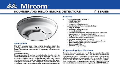
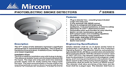
SOUNDER AND RELAY SMOKE DETECTORS SERIES Full line of options including dB sounder C relay thermal sensor the i3 feature set including design base included terminals to octagonal single gang and 4 square back boxes or direct to the ceiling Lock attachment to the base cover and chamber maintenance signaling compensation and smoothing algorithms ed sensitivity measurement color LEDs Walk loop testing Speci cations smoke detector shall be an i3 Series model listed Underwriters Laboratories UL 268 for Fire Protection Systems The detector shall be a combination equipped with a sounder model 4WTA B a Form C relay model 2WTR B combination sounder relay model 4WTAR B or an thermal sounder relay model 4WITAR B The shall include a mounting base for mounting to and 4 inch octagonal single gang and 4 inch back boxes with a plaster ring or direct mount to ceiling using drywall anchors connections shall be made by means of SEMS The detector shall allow prewiring of the base and head shall be a plug in type The detector shall have a sensitivity of 2.5 per foot nominal as measured the UL smoke box The detector shall be capable of adjusting its sensitivity by means of drift and smoothing algorithms The detector provide dual color LED indication which blinks to power up normal standby out of sensitivity alarm freeze trouble conditions When used in conjunction the 2W MOD2 module 2 wire models shall include a signal to indicate the need for maintenance the alarm control panel and shall provide a loop testing to verify the circuit without testing each detector When used in conjunction with the RRS MOD all i3 sounder models on a loop shall sound when alarms all shall be synchronized and all sounders be silenced from the panel i3 sounder and relay smoke detectors apply the principles of installation ease intelligence and inspection in a series of specialty conventional ease the i3 series installation is simple with its base and plug in design The base a broad range of back box and direct options and provides ample space for pre the installation To complete the installation the detector plugs into its base with a simple Stop Drop action reduce the likelihood of nuisance alarms all i3 are equipped with both drift compensation and algorithms These capabilities minimize both and long term causes of nuisance alarms such as interference and dust accumulation When connected the 2W MOD2 loop test maintenance module or an i3 panel 2 wire i3 detectors can generate a remote signal when they are in a maintenance or trouble condition To measure the sensitivity of any detector the SENS RDR displays the reading in terms percent per foot obscuration within seconds inspection i3 line red and green LEDs simplify local status during power up standby alarm maintenance freeze trouble conditions When in alarm i3 sounder generate an 85dB temporal tone If connected to RRS MOD reversing relay synchronization module all sounders on the loop will activate when one detector is in Additionally the RRS MOD synchronizes the output all i3 sounders to ensure a clear audible signal Should application call for differentiating between a local and a alarm the i3 line offers an isolated thermal model initiates a local alarm when smoke is detected and general alarm when the thermal sensor is activated reserves the right to make changes at any time without notice in prices colours materials components equipment speci cations and models and also to discontinue models TO BE USED FOR INSTALLATION PURPOSES NUMBER Speci cations Voltage 12 24 V non polarized 8.5 V 35 V 10 V 35 V Ripple Voltage of applied peak to peak Current 50 maximum average 50 maximum average Standby Current 100 n a Contact Ratings n a 0.5 A 30V AC DC C Contact Ratings 30V AC DC Modes Mode up standby of sensitivity trouble LED every 10 secs every 5 secs LED every 10 secs every 5 secs every 10 secs Speci cations Temperature Range 0 Humidity Range to 95 RH non condensing nominal Terminals AWG Sensor 57.2 xed Trouble 5 including base inches 134 mm diameter inches 51 mm height Alarm Current 130 mA limited by control panel 4WTA B 4WTR B 35 mA 4WITAR B 50 mA Up Sequence for LED Indication LED status indication seconds oz 200 grams 3 octagonal back box 4 inch octagonal back box Single gang back box 4 inch square back box with a ring Direct mount to ceiling Information Number Thermal Current mA max limited by control panel mA max limited by control panel mA mA mA mA Series Reversing relay synchronization module Series 2 wire loop test maintenance module Series Sensitivity Reader Series Retro t Adapter Bracket Series Removal Replacement Tool TO BE USED FOR INSTALLATION PURPOSES by Interchange Way Ontario L4K 5W3 905 660 4655 905 660 4113 Witmer Industrial Estates Falls NY 14305 Free 888 660 4655 Toll Free 888 660 4113 page http www mircom com Email mail mircom com 5148 1