Mircom CAT-5265 CSIS-202A1 Supervised Signal Isolator Module (English)

File Preview
Click below to download for free
Click below to download for free
File Data
| Name | mircom-cat-5265-csis-202a1-supervised-signal-isolator-module-english-0371459826.pdf |
|---|---|
| Type | |
| Size | 1.09 MB |
| Downloads |
Text Preview
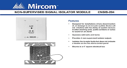
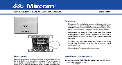
SUPERVISED SIGNAL ISOLATOR MODULE Operates with bells and horns Provides 2 supervised isolator outputs Signals the fire alarm control panel for a short or on the suite signals Mounts in a 4 square electrical box Area on mounting plate for labeling the suite Designed for installations where disconnection or damage to an in suite audible device will interfere with the ability of system audible Ratings In Current Current 0.0 A A Current 24 FWR 24 VDC mA MAX per suite CSIS 202A1 is a signal isolator which provides two isolator outputs These isolators remove the horns or strobes which follow it out of the circuit there be a trouble short This feature provides of the signal circuit that is should an isolated horn or strobe malfunction the rest of the bells or strobes will continue to function Diagram SQUARE ELECTRICAL BOX DEEP INCH PLASTER RING OPTIONAL SIGNAL ISOLATOR Model CSIS 202A1 PLATE SCREWS SUITE USING A MARKER PLATE reserves the right to make changes at any time without notice in prices colours materials components equipment specifications and models and also to discontinue models TO BE USED FOR INSTALLATION PURPOSES NUMBER Wiring Diagrams Wiring of the CSIS 202A1 Supervised Signal Isolator Module ROOM BELL FIRE ALARM SIGNAL CIRCUIT CSIS 202A1 ISOLATOR ROOM BELL TO FIRE ALARM CIRCUIT FOR WIRING NEXT OR LINE ARE SHOWN IN THE DRAW INGS BUT THEY REPRESENT AND STROBES AS WELL Wiring of the CSIS 202A1 Supervised Signal Isolator Module using SIGSM 100 Silence Switch Module CSIS 202A1 ISOLATOR SWITCH BELL BELL SWITCH FIRE ALARM SIGNAL CIRCUIT NON ISOLATED BELL NON ISOLATED BELL NEXT OR TO FIRE ALARM CIRCUIT FOR WIRING All unused screw terminals must be tightened to prevent shorting to front plate For proper system operation refer to detailed installation instructions provided with control panel and local installation standards Wiring supervised by the Fire Alarm Control Panel as per Code Refer to signal device instruction for wiring gauge information Subtract 0.1A from the total signal circuit current when using any number of these isolators i e 1.7A subtract 0.1A equals 1.6A available signaling when using isolators Information Signal Isolator Module Interchange Way Ontario L4K 5W3 905 660 4655 905 660 4113 Witmer Industrial Estates Falls NY 14305 Free 888 660 4655 Toll Free 888 660 4113 www mircom com mail mircom com INFORMATION IS FOR MARKETING PURPOSES AND NOT INTENDED TO DESCRIBE THE PRODUCTS complete and accurate technical information relating performance installation testing and certification refer technical literature This document contains intellectual of Mircom The information is subject to change by without notice Mircom does not represent or warrant or completeness 5265 2