Mircom I56-3311 MIX-2251AP TAP-TMAP (English)

File Preview
Click below to download for free
Click below to download for free
File Data
| Name | mircom-i56-3311-mix-2251ap-tap-tmap-english-6790854213.pdf |
|---|---|
| Type | |
| Size | 871.59 KB |
| Downloads |
Text Preview
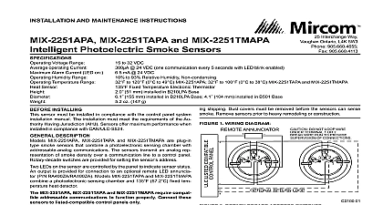
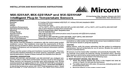
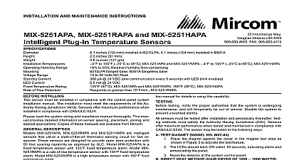
INSTALLATION AND MAINTENANCE INSTRUCTIONS MIX 2251TAP and MIX 2251TMAP Photoelectric Smoke Sensors Voltage Range operating Current Alarm Current LED on Humidity Range Temperature Range Sensor to 32 VDC 24 VDC one communication every 5 seconds with LED blink enabled mA 24 VDC to 93 Relative Humidity Non condensing to 120 0 to 49 MIX 2251AP 32 to 100 0 to 38 MIX 2251TAP and MIX 2251TMAP Fixed Temperature Electronic Thermistor 51 mm installed in B210LP Base 155 mm installed in B210LP Base 4.1 104 mm installed in B501 Base oz 147 g Interchange Way Vaughan Ontario L4K 5W3 905.660.4655 Fax 905.660.4113 INSTALLINg sensor must be installed in compliance with the control panel system manual The installation must meet the requirements of the Au Having Jurisdiction AHJ Sensors offer maximum performance when in compliance with the National Fire Protection Association NFPA NFPA 72 DESCRIPTION MIX 2251AP MIX 2251TAP and MIX 2251TMAP are plug in type sensors that combine a photoelectronic sensing chamber with ad communications The sensors transmit an analog rep of smoke density over a communication line to a control panel switches are provided for setting the sensor address LEDs on the sensor are controlled by the panel to indicate sensor status output is provided for connection to an optional remote LED annunciator RA400Z RA100Z Models MIX 2251TAP and MIX 2251TMAP combine photoelectronic sensing chamber and 135 57.2 fixed temperature detector MIX 2251AP MIX 2251TAP and MIX 2251TMAP require compatible communications to function properly Connect these sen to listed compatible control panels only recommends spacing sensors in compliance with NFPA 72 In low flow applications with smooth ceilings space sensors 30 feet apart For information regarding sensor spacing placement and special appli refer to NFPA 72 or the System Smoke Detector Application Guide from Mircom Applications MIX 2251AP and MIX 2251TAP are listed for use in ducts Duct Applications Guide A05 1004 XX for details on pendant mount ap Note These products are not listed for use inside duct smoke de gUIDE wiring must be installed in compliance with the National Electrical Code local codes and any special requirements of the Authority Hav Jurisdiction Proper wire gauges should be used The installation wires be color coded to limit wiring mistakes and ease system troubleshoot Improper connections will prevent a system from responding properly in event of a fire power from the communication line before installing sensors Wire the sensor base supplied separately per the wiring diagram figure Set the desired address on the sensor address switches see figure 2 Install the sensor into the sensor base Push the sensor into the base turning it clockwise to secure it in place After all sensors have been installed apply power to the control unit and the communication line Test the sensor s as described in the TESTING section of this manual covers provide limited protection against airborne dust particles dur shipping Dust covers must be removed before the sensors can sense Remove sensors prior to heavy remodeling or construction 1 WIRINg DIAgRAM ANNUNCIATOR DO NOT LOOP WIRE TERMINAL 1 OR 2 WIRE RUN TO PROVIDE OF CONNECTIONS RETURN LOOP 2 ROTARy DECADE ADDRESS SWITChES 0 0 MIX 2251AP MIX 2251TAP and MIX 2251TMAP include a tamper capability that prevents their removal from the bracket without the of a tool Refer to the base manual for details on making use of this testing notify the proper authorities that the system is undergoing and will temporarily be out of service Disable the system to unwanted alarms sensors must be tested after installation and periodically thereafter Test methods must satisfy the Authority Having Jurisdiction AHJ Sensors maximum performance when tested and maintained in compliance with 72 sensor can be tested in the following ways functional Magnet Test P N M02 04 01 or M02 09 00 This sensor can be functionally tested with a test magnet The test mag electronically simulates smoke in the sensing chamber testing the electronics and connections to the control panel Hold the test magnet in the magnet test area as shown in figure 3 The sensor should alarm the panel Two LEDs on the sensor are controlled by the panel to indicate sen status Coded signals transmitted from the panel can cause the to blink latch on or latch off Refer to the control panel technical for sensor LED status operation and expected delay to Smoke Entry Aerosol generator gemini 501 The GEMINI model 501 aerosol generator can be used for smoke entry Set the generator to represent 4 ft to 5 ft obscuration as de in the GEMINI 501 manual Using the bowl shaped applicator aerosol until the panel alarms Additionally canned aerosol simu smoke canned smoke agent may be used for smoke entry testing the smoke detector Tested and approved aerosol smoke products are Smoke Detector Tester model 25S available from Home Safeguard and Chekkit Smoke Detector Tester models CHEK02 and available from SDi When used properly the canned smoke will cause the smoke detector to go into alarm Refer to the man published instructions for proper use of the canned smoke aerosol simulated smoke canned smoke agent formulas will vary manufacturer Misuse or overuse of these products may have long term effects on the smoke detector Consult the canned smoke agent published instructions for any further warnings or caution For MIX 2251TMAP smoke entry testing should be performed immedi following the magnet test Magnet test initiates an approximately minute period when the detector signal processing software rou are not active Failure to first perform the magnet test will introduce time delay before the detector alarms Direct heat Method hair Dryer of 1000 1500 watts MIX 2251TAP MIX 2251TMAP only A hair dryer of 1000 1500 watts should be used to test the thermistors the heat toward either of the two thermistors holding the heat approximately 12 inches from the detector in order to avoid dam the plastic housing The detector will reset only after it has had suf time to cool Make sure both thermistors are tested individually sensor that fails any of these tests should be cleaned as described under and retested If the sensor fails after cleaning it must be re testing is complete restore the system to normal operation and notify proper authorities that the system is back in operation 3 TEST MAgNET POSITION MAGNET removing the detector notify the proper authorities that the smoke system is undergoing maintenance and will be temporarily out of Disable the zone or system undergoing maintenance to prevent un alarms Remove the sensor to be cleaned from the system Remove the sensor cover by pressing firmly on each of the four removal that hold the cover in place Vacuum the screen carefully without removing it If further cleaning is continue with Step 4 otherwise skip to Step 7 Remove the chamber cover screen assembly by pulling it straight out Use a vacuum cleaner or compressed air to remove dust and debris the sensing chamber Reinstall the chamber cover screen assembly by sliding the edge over sensing chamber Turn until it is firmly in place Replace the cover using the LEDs to align the cover and then gently it until it locks into place Make sure that the thermistors do become bent under the cover on MIX 2251TAP and MIX 2251TMAP Reinstall the detector Test the detector as described in TESTING Reconnect disabled circuits Notify the proper authorities that the system is back on line 4 SENSOR ASSEMBLy AND