Mircom I56-3316 MIX-M501MAP (English)

File Preview
Click below to download for free
Click below to download for free
File Data
| Name | mircom-i56-3316-mix-m501map-english-5278031964.pdf |
|---|---|
| Type | |
| Size | 855.37 KB |
| Downloads |
Text Preview
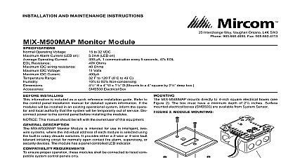
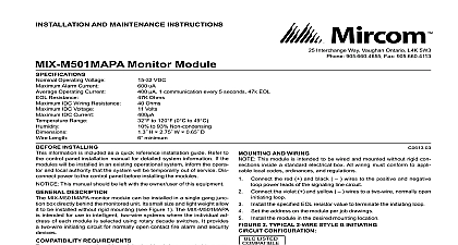
INSTALLATION AND MAINTENANCE INSTRUCTIONS VDC uA 1 communication every 5 seconds 47k EOL Ohms Ohms Volts to 120 0 to 49 to 93 Non condensing H 2.75 W 0.65 D minimum Monitor Module Operating Voltage Alarm Current Operating Current Resistance IDC Wiring Resistance IDC Voltage IDC Current Range Length INSTALLINg information is included as a quick reference installation guide Refer to control panel installation manual for detailed system information If the will be installed in an existing operational system inform the opera and local authority that the system will be temporarily out of service Dis power to the control panel before installing the modules This manual should be left with the owner user of this equipment DESCRIPTION MIX M501MAP monitor module can be installed in a single gang junction directly behind the monitored unit Its small size and light weight allow it be installed without rigid mounting see Figure 1 The MIX M501MAP is for use in intelligent two wire systems where the individual address each module is selected using rotary decade switches It provides a two initiating circuit for normally open contact fire alarm and security devices REqUIREMENTS ensure proper operation this module should only be connected to a com control panel 1 LISTED Interchange Way Vaughan Ontario L4K 5W3 905.660.4655 Fax 905.660.4113 AND WIRINg This module is intended to be wired and mounted without rigid con inside a standard electrical box All wiring must conform to appli local codes ordinances and regulations Connect the red and black wires to the positive and negative power leads of the signaling line circuit Connect the violet and yellow wires to a two wire normally open loop Install the specified EOL resistor value to terminate the initiating loop Set the address on the module per job drawings the module in the desired mounting location 2 TyPICAL 2 WIRE STyLE B INITIATINg CONfIgURATION LINE CIRCUIT SLC WIRING IS AND LIMITED 865 6 7 8 9 EOL Mircom