Mircom I56-3323 MIX-M500SAPA (English)
File Preview
Click below to download for free
Click below to download for free
File Data
| Name | mircom-i56-3323-mix-m500sapa-english-2937154608.pdf |
|---|---|
| Type | |
| Size | 1.47 MB |
| Downloads |
Text Preview
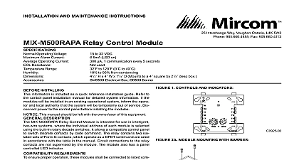
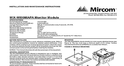
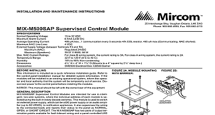
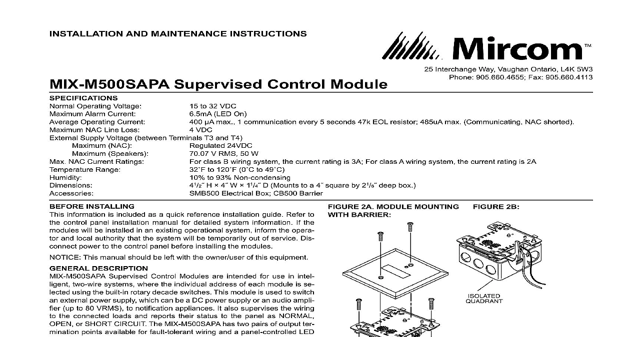
INSTALLATION AND MAINTENANCE INSTRUCTIONS Interchange Way Vaughan Ontario L4K 5W3 905.660.4655 Fax 905.660.4113 to 32 VDC LED On max 1 communication every 5 seconds 47k EOL resistor 485uA max Communicating NAC shorted VDC Supervised Control Module Operating Voltage Alarm Current Operating Current NAC Line Loss Supply Voltage between Terminals T3 and T4 NAC Speakers NAC Current Ratings Range 24VDC V RMS 50 W class B wiring system the current rating is 3A For class A wiring system the current rating is 2A to 120 0 to 49 to 93 Non condensing H 4 W 11 4 D Mounts to a 4 square by 21 8 deep box Electrical Box CB500 Barrier 2A MODULE MOUNTINg fIgURE 2B BARRIER INSTALLINg information is included as a quick reference installation guide Refer to control panel installation manual for detailed system information If the will be installed in an existing operational system inform the opera and local authority that the system will be temporarily out of service Dis power to the control panel before installing the modules This manual should be left with the owner user of this equipment DESCRIPTION Supervised Control Modules are intended for use in intel two wire systems where the individual address of each module is se using the built in rotary decade switches This module is used to switch external power supply which can be a DC power supply or an audio ampli up to 80 VRMS to notification appliances It also supervises the wiring the connected loads and reports their status to the panel as NORMAL or SHORT CIRCUIT The MIX M500SAPA has two pairs of output ter points available for fault tolerant wiring and a panel controlled LED REqUIREMENTS ensure proper operation these modules shall be connected to listed com system control panels only 1 CONTROLS AND 1B jUMPER LOCA MIX M500SAPA mounts directly to 4 inch square electrical boxes see 2A The box must have a minimum depth of 21 8 inches Surface electrical boxes SMB500 are available from Mircom All wiring must conform to applicable local codes ordinances and When using control modules in nonpower limited applications Mircom CB500 Module Barrier must be used to meet UL requirements for separation of power limited and nonpower limited terminals and wiring barrier must be inserted into a 4 junction box and the control must be placed into the barrier and attached to the junction box Fig 2A The power limited wiring must be placed into the isolated quadrant of module barrier Figure 2B Install module wiring in accordance with the job drawings and appropri wiring diagrams Set the address on the module per job drawings Secure module to electrical box supplied by installer as shown in Fig 2A When using the MIX M500SAPA for fire fighter telephone ap remove Jumper J1 and discard The Jumper is located on the as shown in figure 1B The module does not provide ring back when as a fire fighter telephone circuit 3 TyPICAL NOTIfICATION APPLIANCE CIRCUIT CONfIgURATION NfPA STyLE y NOT LOOP WIRE ON TERMINALS 10 11 BREAK WIRE RUN TO SUPERVISION OF CONNECTIONS VDC CIRCUIT MODULES TO COMPATIBLE CONTROL ONLY PANEL PREVIOUS LINE CIRCUIT SLC VDC MAX PAIR RECOMMENDED WIRING SHOWN IS SUPERVISED AND LIMITED NEXT ANY FAULT IN THE POWER SUPPLY IS LIMITED THAT ZONE AND DOES NOT RESULT IN A FAULT IN SEPARATE ZONE VDC POWER SUPPLY REGULATED POWER PER NFPA 70 LISTED FOR PROTECTION WITH BATTERY POLARITIES ARE IN ALARM EOL LISTED EOL RELAY ENERGIZED VDC COIL EOLR 1A NEXT CONTROL MODULE OR END OF LINE RELAY RELAY REQUIRED FOR EACH CIRCUIT SOME PANELS HAVE RELAY BUILT IN AND DO NOT EXTERNAL WIRING REFER TO PANEL MANUAL 4 TyPICAL fAULT TOLERANT NOTIfICATION APPLIANCE CIRCUIT CONfIgURATION NfPA STyLE Z NOT LOOP WIRE ON TERMINALS 10 11 BREAK RUN TO PROVIDE SUPERVISION OF MODULES TO LISTED COMPATIBLE PANELS ONLY VDC POWER SUPPLY REGULATED POWER PER NFPA 70 LISTED FOR FIRE WITH BATTERY BACKUP VDC CIRCUIT PANEL POLARITIES ARE IN ALARM RESISTOR IS AT 9 LISTED EOL SHOWN VDC COIL LINE CIRCUIT SLC VDC MAX TWISTED PAIR RECOMMENDED WIRING SHOWN IS SUPERVISED AND LIMITED NEXT NEXT CONTROL MODULE OR RELAY ONE RELAY FOR EACH CIRCUIT SOME PANELS HAVE RELAY BUILT IN DO NOT REQUIRE EXTERNAL REFER TO PANEL MANUAL ANY FAULT IN THE POWER SUPPLY IS LIMITED THAT ZONE AND DOES NOT RESULT IN A FAULT A SEPARATE ZONE 5 TyPICAL wIRINg fOR SPEAkER SUPERvISION AND SwITChINg NfPA STyLE y CIRCUIT WIRING MUST BE TWISTED PAIR AS A MINIMUM SEE PANEL INSTALLATION MANUAL FOR DETAILED INFORMATION MUST BE SUPERVISED MODULES TO LISTED COMPATIBLE PANELS ONLY ULC PANEL OR DEVICE LINE CIRCUIT SLC VDC MAX PAIR RECOMMENDED CIRCUIT NOT LOOP WIRE AROUND TERMINALS 10 BREAK WIRE TO ENSURE OF CONNECTIONS AMPLIFIER 70.7 Vrms MAX MUST PROVIDE WIRING PER ULC POLARITIES ARE IN ALARM EOL NEXT CONTROL MODULE LAST MUST RETURN WIRES FOR MUST BE LISTED FOR FIRE PROTECTION TO THE RELAY CONTACT RATING TABLE FOR LOAD ANY FAULT IN THE POWER SUPPLY IS LIMITED TO THAT ZONE AND DOES NOT RESULT IN A FAULT IN A SEPARATE ZONE 6 TyPICAL fAULT TOLERANT wIRINg fOR SPEAkER SUPERvISION AND SwITChINg NfPA STyLE Z CIRCUIT WIRING MUST BE TWISTED PAIR AS A MINIMUM SEE PANEL INSTALLATION MANUAL FOR DETAILED INFORMATION MODULES TO LISTED COMPATIBLE CONTROL PANELS ONLY NOT LOOP WIRE AROUND TERMINALS 10 11 MUST BE SUPERVISED CIRCUIT WIRE TO ENSURE OF CONNECTIONS ULC AMPLIFIER 70.7 Vrms MAX MUST PROVIDE WIRING PER ULC EOL RESISTOR INTERNAL AT 8 9 CAPACITORS 100 NONPOLARIZED LEAKAGE POLARITIES ARE IN ALARM NEXT CONTROL MODULE LAST MUST RETURN WIRES FOR ANY FAULT IN THE POWER SUPPLY IS LIMITED TO THAT ZONE AND DOES NOT RESULT IN A FAULT IN A SEPARATE ZONE NEXT PANEL PREVIOUS LINE CIRCUIT SLC VDC MAX PAIR RECOMMENDED WIRING SHOWN IS SUPERVISED AND LIMITED NEXT MUST BE LISTED FOR FIRE REFER TO THE RELAY RATING TABLE FOR MAXIMUM relay switch contacts are shipped in the standby state open state but may have transferred to the activated closed state during shipping To ensure that switch contacts are in their correct state modules must be made to communicate with the panel before connecting circuits controlled by the module Mircom