Mircom LT-2070 MS-400AP(U) Pull Station Installation Manual

File Preview
Click below to download for free
Click below to download for free
File Data
| Name | mircom-lt-2070-ms-400ap-u-pull-station-installation-manual-9318245670.pdf |
|---|---|
| Type | |
| Size | 835.78 KB |
| Downloads |
Text Preview
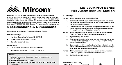
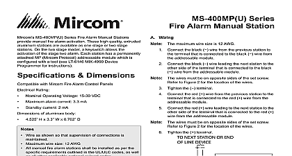
Mircom MS 400AP U Series Fire Alarm Manual Stations manual fire alarm activation These high quality die cast stations are available as one stage or two stage stations the two stage model use a key to activate the stage two Each station has a permanently attached AP addressable which has a pair of dials for setting the address Dimensions with Mircom Fire Alarm Control Panels Rating Operating Voltage VDC alarm current 24V mA operating current 600 4.55 H x 3.3 W x 2 D MS 407AP U 4.55 H x 3.3 W x 2.1 D MS 407AP U Operating Voltage VDC alarm current 24V operating current 400 Wire as shown so that supervision of connections is Maximum wire size 12 AWG All manual fire alarm stations shall be installed as per specific requirements outlined in the UL ULC codes well as all other applicable national or local codes acceptance is subject to the local authority having the manual station guide covers these models Intelligent Single Stage Manual Station AP Intelligent Two Stage Manual Station AP Intelligent Single Stage Manual Station AP with N C switch suffix U indicates a USA version of kit MS 401AP U MS 407AP U 2 mounting screws 1 glass MS 402AP 2 mounting screws 2 stage two keys 1 glass rod sold separately separately Wiring The maximum wire size is 12 AWG Connect the black wire from the previous station to terminal that is connected to the black wire from addressable module Connect the black wire leading the next station to the side of the terminal that is connected to the black wire from the addressable module Series Alarm Manual Station The wires must be on opposite sides of the set screw to Figure 2 for the location of the wires Tighten the terminal Connect the red wire from the previous station to the that is connected to the red wire from the module Connect the red wire leading to the next station to the side of the terminal that is connected to the red from the addressable module The wires must be on opposite sides of the set screw to Figure 2 for the location of the wires Tighten the terminal NEXT STATION OR OF LINE DEVICE BLACK RED FUNCTION SWITCH ONLY 1 Wiring Diagram BOTH ON SIDES THE SET SCREW BOTH ON THE SIDE AS SET SCREW ADDRESSABLE ADDRESSABLE 2 Close up of terminals showing correct wiring Interchange Way ON L4K 5W3 888 660 4655 888 660 4113 Witmer Industrial Estates Falls NY 14305 888 660 4655 LT 2070 Rev 2 July 2018 Series Alarm Manual Station the manual station in of fire the alarm down the handle handle is now hanging down A qualified person must the station See Resetting the manual station below the stage two alarm MS 402AP only the stage two key into the keyhole inside the station then turn the key This keyhole is accessible only after alarm has been pulled stage two alarm activates stage two alarm will activate automatically a certain of time after the handle has been pulled This is set in the Fire Alarm Control Panel You can the stage two alarm from activating automatically using the Automatic Alarm Signal Timer Cancel on the Fire Alarm Control Panel Refer to the Fire Control Panel manual for instructions the manual station the station does not reset the alarm a small flathead screwdriver into the hole in the front of handle Make sure that the end of the screwdriver is on top of the latch inside the station The screwdriver push down this latch order for the handle to close Close the handle and at the same time move the handle of screwdriver up See Figure 4 you close the handle the screwdriver acts as a lever to the latch down allowing the handle to close will hear a click when the handle is closed and the station reset the glass rod break glass into the hole on the right See Figure 4 Reset the Fire Alarm Control Panel to reset the alarm Setting the addressable module MS 402AP Pull the module out of the bracket to set the AP addressable module allows for an address range of 1 to The TENS dial goes to 15 unlike the CLIP module where TENS dial goes to 9 module is set to 1 by default For proper operation must change this to a different address dial dial following table shows how to set the dials for some example set this address the dials are set to a number higher than 99 and the panel only CLIP then the panel will see the device as an device at address 0 MS 401AP U and MS 407AP U count as one address is set by the dials on the addressable module MS 402AP counts as two addresses The first address the PULL handle and is set by the dials on the module The second address is one number higher the dial setting and represents the switch activated by the two key example if you set the dials on the MS 402AP to the address then M represents the PULL handle and M 1 represents the two key switch the MS 402AP counts as two addresses set the dial address at least 1 below the value If the panel supports only CLIP set the no higher than 98 and if the panel supports AP the address no higher than 158 Mounting Pull down the handle so that the station is open Mount the station to a surface mounted box with the 2 screws Refer to Figure 3 Close the station Follow the instructions under the manual station on this page STATION GANG BOX 3 Mounting the manual station 4 Resetting the manual station LT 2070 Rev 2 July 2018