Mircom LT-2078 Wall and Ceiling Notification Appliances (English)

File Preview
Click below to download for free
Click below to download for free
File Data
| Name | mircom-lt-2078-wall-and-ceiling-notification-appliances-english-0716329458.pdf |
|---|---|
| Type | |
| Size | 3.54 MB |
| Downloads |
Text Preview
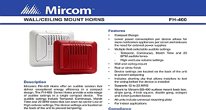
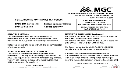
MGC Interchange Way ON 5W3 1 888 660 4655 1 888 660 4113 Witmer Industrial Estates Falls NY and strobe and FHS 400 RR wall mounted horn and and FHS 400C RR ceiling mounted horn strobe WW indicates a white unit and RR indicates a red and Ceiling Noti cation Appliances manual applies to the following models only and FH 400 RR wall and ceiling mounted horn only and FS 400 RR wall mounted strobe and FS 400C RR ceiling mounted strobe Speci cations temperature range ash rate Voltage Voltage Range RMS 16 33 VDC VFWR terminal wire gauge AWG to 12 AWG environment indoor use only not change factory applied nishes for all Models to 50 32 to 122 to 93 Hz 24 VDC 24 VFWR 27 32 123 mm kit includes x 3 8 screw clip 27 32 mm 27 32 mm 8 32 x 3 4 screws x2 6 32 x 3 4 screws x 2 cover and width all models of the Optional Mounting Box BB 400R W plate with screws clip and protective cover 27 32 123 mm dimensions 1 1 16 27 mm 51 64 mm Rev 2 March 2017 switches for setting options selector tab Clip order to test the wiring place the shorting on the middle two terminals after wiring the shorting clip before mounting device clip candela setting the Candela FS 400 FHS 400 FHS 400C only candela can be set to 15 30 75 15 75,110 and 185 for FS 400 FHS 400 The factory default setting is 15 The 185 candela setting is not available on ceiling units Remove the plastic selector tab from the back of the device Re insert the selector tab into the notch that is labeled with the the DIP Switches DIP switches 2 and 3 are not used 1 Input Switch 1 24 Non 4 and 5 Signal Rate Switch 4 DIP Switch 5 Rate default ON BPM Use Non synchronized the appliances do not to be synchronized Synchronized when is required through a sync module or synchronization on the unit 6 Horn volume Switch 6 default switch 6 switch 1 OFF the information in this document to determine the total current draw of the devices The total current draw of the must not exceed the power supply of the panel In all cases the installer should consider the voltage drop to that the last device on the circuit operates within its rated voltage absolute maximum number of devices on one is 100 The absolute maximum impedance wall mounted devices at 15 candela is 150 FACP previous next or of line terminal wire gauge 22 AWG to 12 AWG Wiring must be in accordance with CSA Canadian Electrical Code Part I Safety for Electrical Installations Section 32 NFPA 70 Rev 2 March 2017 to the Wall or Ceiling recommends spacing noti cation appliances in compliance with CAN ULC S524 and NFPA 72 the unit with the MGC logo at the top The mounting plate is compatible with 3 by 2 single gang device boxes by 4 double gang boxes 4 by 2 single gang utility boxes standard 4 by 4 boxes and standard 4 octagon See below for a description of the holes to use for each box the mounting plate to the box with 2 4 screws to the Optional Mounting Box BB 400R W recommends spacing noti cation appliances in compliance with CAN ULC S524 and NFPA 72 the unit with the MGC logo at the top the unit on to the mounting the unit with the 4 40 x 3 8 and snap the nameplate over screw the mounting plate to the mounting with the 4 screws the unit on to the mounting the nameplate and screw a screwdriver into the slot at the of the unit and turn it to separate the from the mounting plate the unit with the 4 40 x 3 8 and snap the nameplate over screw Options C 3 by 2 single gang device box 3 3 4 by 4 double gang box 4 by 2 single gang utility box standard 4 by 4 box standard 4 octagon box Rev 2 March 2017 61 64 mm RMS Currents mA Strobe Operating RMS Currents mA Regulated 24 VDC Regulated 24 VFWR Strobe Operating RMS Currents mA Regulated 24 VDC The 185 candela setting is not available on ceiling units Horn Operating RMS Currents mA 24 VFWR 3 4 mm 35 64 mm 24 all tones 24 all tones Horn Strobe Operating RMS Currents mA 24 VDC 24 VFWR Temporal Tone Tone Volume Volume Horn Strobe Operating RMS Currents mA 24 VFWR Tone Volume Tone Volume 24 VDC Temporal Tone Volume The 185 candela setting is not available on ceiling units Tone Volume Tone Volume Tone Volume 61 64 mm Temporal tone volume is of March and 20 rates as well 3 4 mm Rev 2 March 2017 Ratings Reverberant Ratings per UL464 dBA 10 ft for FH 400 FHS 400 FHS 400C Pattern VDC 16 VFWR Regulated VDC Regulated VFWR BPM BPM VDC VDC VFWR VFWR Anechoic Ratings per CAN ULC S525 dBA 3 m for FH 400 FHS 400 Pattern VDC 16 VFWR Regulated VDC Regulated VFWR Directional Sound Characteristics for FH 400 FHS 400 FHS 400C Axis 45 61 90 dbA dbA dbA Axis 49 61 90 dbA dbA dbA Rev 2 March 2017 Output Dispersion The following values are shown as percentages of the rated light output at any candela setting of Candela Rating Dispersion to Floor for and FS 400 for FHS and FS 400 devices cannot operate on coded power supplies of Warranties and Limitation of Remedies and Liability Systems Corp or the makes no warranty of merchantability or tness for a particular purpose with respect to its goods nor is any other warranty expressed or implied except for the warranty contained herei