Mircom LT-6022 IPS 4848 Instruction Sheet

File Preview
Click below to download for free
Click below to download for free
File Data
| Name | mircom-lt-6022-ips-4848-instruction-sheet-8093475162.pdf |
|---|---|
| Type | |
| Size | 1.19 MB |
| Downloads |
Text Preview
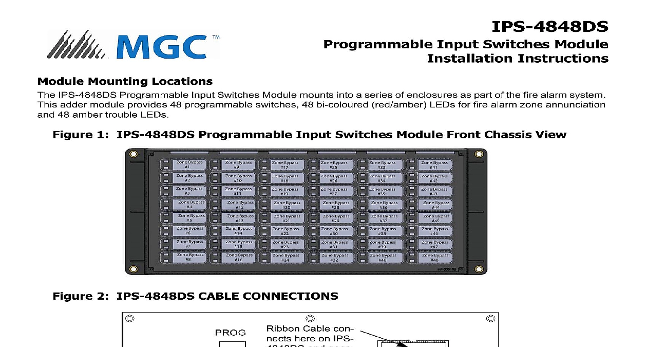
IPS 4848DS Input Switches Module Instructions Mounting Locations IPS 4848DS Programmable Input Switches Module mounts into a series of enclosures as part of the fire alarm system adder module provides 48 programmable switches 48 bi coloured red amber LEDs for fire alarm zone annunciation 48 amber trouble LEDs 1 IPS 4848DS Programmable Input Switches Module Front Chassis View 2 IPS 4848DS CABLE CONNECTIONS Bypass 1 Bypass 2 Bypass 3 Bypass 4 Bypass 5 Bypass 6 Bypass 7 Bypass 8 Bypass 9 Bypass 10 Bypass 11 Bypass 12 Bypass 13 Bypass 14 Bypass 15 Bypass 16 Bypass 17 Bypass 18 Bypass 19 Bypass 20 Bypass 21 Bypass 22 Bypass 23 Bypass 24 Bypass 25 Bypass 26 Bypass 27 Bypass 28 Bypass 29 Bypass 30 Bypass 31 Bypass 32 Bypass 33 Bypass 34 Bypass 35 Bypass 36 Bypass 37 Bypass 38 Bypass 39 Bypass 40 Bypass 41 Bypass 42 Bypass 43 Bypass 44 Bypass 45 Bypass 46 Bypass 47 Bypass 48 Cable con here on IPS and goes the next display Ribbon IN Cable is permanently attached and connects to previous Ribbon connector to the fire alarm manual for further information regarding the IPS 4848DS TO USERS INSTALLERS AUTHORITIES HAVING JURISDICTION AND OTHER INVOLVED PARTIES product incorporates field programmable software In order for the product to comply with the requirements in the Standard for Units and Accessories for Fire Alarm Systems UL 864 and the Standard for Control Units for Fire Alarm Systems CAN ULC certain programming features or options must be limited to specific values or not used at all as indicated below feature or option in UL 864 Y N settings Switch Alarm by pressing Signal button again permitted in UL 864 button can be used to the signals after they been silenced Rev 0 Dec 2018


