Mircom LT-6032 ALCN-792MISO ALCN-792D

File Preview
Click below to download for free
Click below to download for free
File Data
| Name | mircom-lt-6032-alcn-792miso-alcn-792d-4735028961.pdf |
|---|---|
| Type | |
| Size | 885.17 KB |
| Downloads |
Text Preview
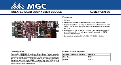
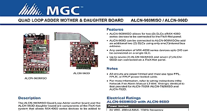
ALCN 792M ALCN 792MISO and Loop Adder Motherboard and Daughter Board Instructions ALCN 792M Quad Loop Adder and the ALCN 792MISO Isolated Quad Loop Adder module provide two loops plus an additional two loops as part of the daughter board ALCN 792D which is mounted over the The Quad Loop Adder module may be mounted over the main chassis of the Network Alarm Panel or on any chassis that supports adder boards This module is mounted using four 6 screws and if four 1 1 2 spacers Switches 1 2 power is supplied to the board via cable from the main chassis board or from the loop controller module into the P1 POWER IN connector Connect the P2 OUT connector to the next loop controller module or other adder module power cable is supplied with this module RS 485 cable comes attached at P3 on ALCN 792M and P4 on ALCN and is either connected to P3 of the main fire alarm controller module or from the previous loop controller module or other adder board If the next controller module is used connect the RS 485 out at P4 on ALCN 792M or P3 ALCN 792MISO to the next loop controller module if it is not used leave without the DIP switches to set the binary address of the board SW1 1 is the lowest digit and ON is active For example an address of two would be created turning SW1 1 OFF SW1 2 ON and DIP switches SW1 3 to SW1 8 OFF Refer to switch settings in table below is the addressable loop for all initiating devices Wire the loop as shown in the Fire Alarm Manual is the addressable loop for all initiating devices Wire the loop as shown in the Fire Alarm Manual the loops are shielded connect the shields to the terminals marked COM To the board reporting a ground fault do not connect shields on SLC lines to ground Unshielded wiring is preferred and ALCN 792MISO Factory use only Leave open Factory use only Leave closed 3 pin jumper Normally set to 1 2 can be set to 2 3 to prevent noise from System Sensor sounder bases on Loop 1 Pin 1 is marked with a dot 3 pin jumper Normally set to 1 2 can be set to 2 3 to prevent noise from System Sensor sounder bases on Loop 2 Pin 1 is marked with a dot on ALCN 792MISO Factory use only Leave closed Debug Interface only Port connection is for factory use only page 4 connection is for factory use only LT 6032 Rev 3.2 May 2019 DIP Switch Setting the DIP switches on SW1 starting at address 1 for the first ALCN 792M ALCN 792MISO adder and consecutively up to for the next six ALCN 792M ALCN 792MISO modules Refer to the Network Fire Alarm Manual for the maximum ALCN 792M ALCN 792MISO adder modules allowed per node ALCN 792M ALCN 792MISO Loop Adder Module Address Setting DIP SWITCH SW1 to Network Fire Alarm Manual as to whether addresses 5 6 and 7 are available Module Layout location of Loop 1 and 2 terminals on ALCN 792M are shown in Figure 1 below Also shown are the power in and cable locations DIP switch location and jumper locations 1 ALCN 792M Quad Loop Adder Module 1 2 USED S OUT IN 1 LED heartbeat leave closed 2 LED open flashing LED for board processor Board PORT SWITCH SWITCHES ARE FOR THIS ADDRESS SW1 1 THE LEAST SIGNIFICANT BINARY ACTIVE IS ON CABLE OUT for ALCN 792M shaded holes are Daughter board 2 holes and 2 holes are for the ALCN Quad Loop module CABLE IN All circuits are power limited and must use type FPL FPLR or FPLP power limited cable Loop wiring maximum loop resistance is 40 ohms total These lines are power limited and fully For complete wiring instructions refer to the LT 894 LT 894SEC Network Fire Alarm Manual LT 6032 Rev 3.2 May 2019 Module Layout location of Loop 1 and 2 terminals on ALCN 792MISO are shown in Figure 2 below Also shown are the power in out cable locations DIP switch location and jumper locations 2 ALCN 792MISO Isolated Quad Loop Adder Module 1 2 USED S OUT flashing heartbeat 1 LED 2 LED PORT use only shaded holes are Daughter board 2 holes and 2 holes are for the ALCN Quad Loop module leave open leave closed flashing LED for on processor Board SWITCH SWITCHES ARE FOR THIS ADDRESS SW1 1 THE LEAST SIGNIFICANT BINARY ACTIVE IS ON CABLE OUT CABLE IN for ALCN 792MISO All circuits are power limited and must use type FPL FPLR or FPLP power limited cable Loop wiring maximum loop resistance is 40 ohms total These lines are power limited and fully Wired in the same manner as the ALCN 792M Refer to wiring instructions in the LT 894 LT 894SEC Fire Alarm Manual LT 6032 Rev 3.2 May 2019 Daughter Board Installation location of Loop 1 and 2 terminals on ALCN 792D are shown in Figure 3 below Also shown are the jumper ALCN 792D Daughter Board provides another two addressable loops when connected to the ALCN 792M Quad Loop Adder Board This daughter board is mounted over the ALCN 792M ALCN 792MISO using four screws and spacers provided Wire the two addressable loops on the ALCN 792D Daughter Board in the same as the ALCN 792M ALCN 792MISO addressable loops are wired the loops have shielding connect the shields to the terminals marked COM To prevent the board reporting a fault do not connect shields on SLC lines to earth ground Unshielded wiring is preferred 3 ALCN 792D Daughter Board mounting holes mount to board screws and spacers provided S 3 4 Normally set to can be set to 2 3 prevent noise from System Sensor bases on 3 Main Board Connector P6 for ALCN 792D Normally set to can be set to 2 3 prevent noise from System Sensor bases on 4 ribbon cable this board to the P6 All circuits are power limited and must use type FPL FPLR or FPLP power limited cable Loop wiring maximum loop resistance is 40 ohms total These lines are power limited and fully For complete wiring instructions refer to the Network Fire Alarm Manual LT 6032 Rev 3.2 May 2019