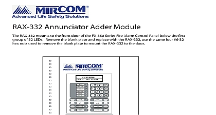
Mircom LT-6057 DSPL-420-16TZDS Installation Instruction (English)

File Preview
Click below to download for free
Click below to download for free
File Data
| Name | mircom-lt-6057-dspl-420-16tzds-installation-instruction-english-5421860973.pdf |
|---|---|
| Type | |
| Size | 1.48 MB |
| Downloads |
Text Preview
DSPL 420 16TZDS DSPL 420 16TZDS is a main display control interface for a main panel in a FleX Net MMX or a FX 2000 It is designed to mount in any standard display window cut out found on the doors in the MMX and FX 2000 series This display is functionally equivalent to the FleX Net and classic FX main display but more compact DSPL 420 16TZDS has a 4 line 20 character back lit LCD display with 4 cursors buttons and an Enter to navigate the LCD menu items as well as Menu Cancel and Information buttons The display features 16 configurable bi coloured LEDs 4 Queue Buttons with LED Indicators and 8 control each with it own LED Indicator The display also includes LEDs to indicate AC On Ground Fault CPU Fault Indicators and Controls 1 Indicator and Control locations on the DSPL 420 16TZDS controls and for Alarm and Monitor On Fault configurable zone and 16 indicators Fault Display lines characters buttons Enter button and Indicators for Silence General Alarm Alarm Signal Cancel Drill System Reset Test and Spare Buttons indicator are amber trouble or supervisory red alarm or green AC On and may illuminate steady or at one of two flash rates Flash 120 flashes per minute 50 duty cycle flash 20 flashes per minute 50 duty cycle Rev 0 May 2014 Page 1 of 4 General Alarm LED and pushbutton and the Automatic Alarm Signal Cancel LED and are active only on a system configured for Stage Labels for Buttons and Indicators and indicators are supplied with paper labels These labels slide into the plastic label templates on face of the panel Paper labels allow for easy English French selections and custom printed zone Indicators Buzzer is activated by any of the following Alarm Trouble Steady Fast Rate Trouble Rate Configurable for silence or for sounding at the Fast Rate To meet UL 864 requirements set the Monitor buzzer for silence the Buzzer is turned on in response to a Non Latching Trouble or Supervisory it will be turned off if the condition it goes away and there is no other reason for it to be on AC On Indicator is activated steady green while the main AC power is within acceptable levels It is turned off the level falls below the power fail threshold and the panel is switched to standby battery power common Alarm LED flashes red whenever the Panel is in Alarm An alarm results from any alarm on any point input programmed as Alarm or activation of the manual red General Alarm Button if the panel is set for Two Operation The Alarm Queue LED will go steady once all alarms in the queue have been reviewed using Alarm Queue button Since all Alarms are latched until the Panel is reset the Common Alarm LED will remain until then Common Supv Supervisory LED flashes amber at the Fast Flash Rate when there is a Supervisory Alarm in Panel as the result of any Latching or Non Latching Supervisory Circuit The LED turns off if all Non Latching Circuits are restored and there are no Latching Supervisory Circuits active The Supv Queue LED will steady once all supervisory alarms in the supervisory queue have been reviewed using the Supv Queue Latching Supervisory Alarms remain active until the Panel is reset Common Trouble LED flashes amber at the Trouble Flash Rate when there is any Trouble condition being on the panel It is turned off when all Non Latching Troubles are cleared The Trouble Queue LED will go once all troubles in the trouble queue have been reviewed using the Trouble Queue button LED Monitor Trouble Indicator flashes amber at the Trouble Flash Rate when there is any Monitor condition being on the panel It is turned off when all Monitors are cleared CPU Fault Indicator flashes yellow if the CPU is faulty Drill LED Fire Drill Indicator turns on steady amber while the Fire Drill is active the Panel is configured as Two Stage the Automatic Alarm Signal Cancel Indicator flashes amber at the Fast Rate while the Auto General Alarm Timer is running It turns on steady amber when the Timer is cancelled by the Automatic Alarm Signal Cancel or Signal Silence buttons If the Auto General Alarm Timer times and puts the Panel into General Alarm the indicator is turned off Rev 0 May 2014 Page 2 of 4 On LED Queue LED LED Fault LED LED LED Display Two Stage Operation only the General Alarm Indicator is activated steady red when General Alarm is activated to the red General Alarm button being pushed a General Alarm Initiating Circuit being activated or the Auto Alarm Timer timing out Once the General Alarm Indicator has been turned on it will stay active until the is reset Signal Silence indicator is flashed amber at the trouble rate when the Indication Circuits are Silenced either by Signal Silence button or by the Auto Signal Silence Timer It is turned off when the Signals are re sounded by subsequent Alarm Fault Ground Fault Indicator flashes amber at the Trouble Rate when the Ground Fault Detector detects a Ground on any field wiring It turns off immediately when the Ground Fault is cleared Controls display is a compact 4 line by 20 character back lit alphanumeric LCD It displays information on panel and it devices There are cursor buttons for menu selection and control Information by the LCD display is an alarm log an event log current levels device information and maintenance reports the queue buttons to select a particular queue to review Use the Alarm Queue button to view all alarms Pressing this button will show the latest alarm on the LCD Use and to view all previous alarms Use the Supervisory Queue button to view all Supervisory conditions Pressing this button will show the supervisory information on the LCD display Use and to view all previous supervisory on the LCD display Use the Trouble Queue button to view all trouble conditions Pressing this button will show the latest trouble on the LCD display Use and to view all previous troubles Use the Monitor Queue button to view all monitor conditions Pressing this button will show the latest monitor on the LCD display Use and to view all previous monitor conditions are displayed on the screen according to a priority sequence Queue priority ranking from to lowest is as follows alarm supervisory trouble and monitor If for example you are viewing monitor queue and an alarm occurs the display will immediately display the alarm condition Also if is no activity on the system for 10 seconds after you have pressed a queue button the display will to the highest priority condition four buttons around the Enter Button are used for up previous down Latest left and right selection of on the LCD Display Button This button is used to select a displayed item on the LCD Display Button button is used to cancel an operation Button button is used to initiate the FX 2000N Menu System Button button is used to get more details about a displayed item Rev 0 May 2014 Page 3 of 4 System Reset button causes the Fire Alarm Control Panel and all Circuits to be reset Resets all Latching Trouble Conditions Resets all Initiating Circuits Resets 4 Wire Smoke Supply and Aux Power Supply Reset Turns off all NACs Turns off Signal Silence Ack GA Indicators off Fire Drill Stops and resets all Timers Processes inputs as new events Aux Disconnect is not affected Drill Signal Two Only Button Reset cannot be activated until the Signal Silence Inhibit timer has expired of the Signal Silence button when the Panel is in Alarm turns on the Signal Silence Indicator deactivates and Silenceable NACs Non Silenceable Circuits are unaffected Signals will re sound any subsequent Alarm This button does not function during any configured Signal Silence Inhibit period It also does not function if the NACs are active as the result of a Fire Drill In a Two Stage if the A