Mircom LT-617 RA-1000 Installation and Wiring Manual (English)

File Preview
Click below to download for free
Click below to download for free
File Data
| Name | mircom-lt-617-ra-1000-installation-and-wiring-manual-english-4896532017.pdf |
|---|---|
| Type | |
| Size | 1.05 MB |
| Downloads |
Text Preview
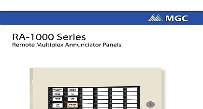
RA 1000 Series Multiplex Annunciator Panels and Wiring Manual Rev 19 2018 of Contents Installation Instructions Switch Settings WIRING 3 DC POWER WIRING 3 DIP switches located on the main are set as 4 FA 1000 FA 300 and MR 2300 Series Panels 4 FX 2000 Panels 5 FleX NetTM and MMXTM Panels 5 FX 3500 FX 3500RCU FX 3318 FX 350 FA 300 FR 320 MR 3500 and MR 2350 Panels 6 RAX 1048TZDS Adder Annunciator Chassis 6 RAM 1032TZDS Main Annunciator Chassis 6 RAM 1016TZDS Main Annunciator Chassis 6 and Features 7 7 Main Annunciator Chassis 7 Main Annunciator Chassis 7 Adder Annunciator Chassis 8 Drain for Battery Calculations 8 Specifications 8 Introduction modular design RA 1000 Series Remote Multiplex Annunciator panels provide a large of annunciation with MGC Analog and Network Fire Alarm Control Panels Tables describe the different main annunciator and adder chassis models Each circuit is a bi colour LED that is automatically configured to match the fire alarm control configuration 1 Annunciator Chassis Descriptions Number main annunciator chassis with 16 added zoned trouble LEDs main annunciator chassis with 32 added zoned trouble LEDs that be expanded with up to four RAX 1048TZDS adder annunciator chassis a maximum of 208 circuit display points adder annunciator chassis with 48 added zoned trouble LEDs Mechanical Installation are five sizes of enclosures available see Table 2 below Model Number 2 Enclosure Dimensions and Capacity MMX BB 1001D R MMX BB 1002D R MMX BB 1003D R MMX BB 1008D R MMX BB 1012D R in in CAN BE MOUNTED STANDARD 4 X 4 BOXES 12.75 1.85 BACKBOX IS SHOWN ANNUNCIATOR CHASSIS BRACKET MODELS used for RAX 1 Mechanical Assembly Diagram GUARD BRACKET The RAM 1032TZDS and the RAM 1016TZDS are supplied with the NP 680 laser label sheet Column 1A or 1B English or French is selected for either a 2 stage 1 stage system and the blank labels are used to print zone information The RAX is supplied with the NP 681 blank laser printable label sheet RA 1000 series of annunciators RAM 1016TZDS RAM 1032TZDS and RAX display Initiating Circuit Status and individual circuit trouble indication and Relay Circuits are not remotely displayed For more details see the Fire Control Panel manual Wiring Instructions RS 485 WIRING RS 485 wiring to the and Module is to be twisted pair as shown in 2 The wire gauge may AWG up to 2000 ft AWG up to 4000 ft 24V DC POWER VDC VDC 2 Wiring Diagram VDC POWER FROM FIRE ALARM CONTROL OR PREVIOUS ANNUNCIATOR VDC POWER TO ANNUNCIATOR FROM FIRE ALARM OR PREVIOUS TWISTED SHIELDED PAIR TO NEXT ANNUNCIATOR SHIELDED PAIR RS 485 wiring from the alarm control panel to the must be point from the fire alarm to the first annunciator to the next annunciator so on No star wiring or T tapping is allowed Each RAM 1016TZDS and RAM 1032TZDS Annunciator Module has a 120 ohm end of line resistor on its RS 485 output terminals is removed on all except the last wired module 24 VDC field wiring needs to be of an appropriate gauge for the number of annunciators the total wiring run length Use the Current Drain for Battery Calculations on page 8 to the maximum current for all annunciators summed together All circuits are power limited and must use type FPL FPLR or FPLP power limited Accidentally connecting any of the 24 VDC wires to the RS 485 wiring will in damage to the annunciator and or to the fire alarm control panel which it is connected 3 Wiring Table for Power to Annunciator Maximum for all Wiring Run to Last Annunciator Loop DIP Switch Settings annunciator assembly main and adder chassis needs to be assigned a unique via the main annunciator DIP Switch SW1 DIP Switch SW2 is used for of some Front Panel located on the main annunciator chassis push buttons when switches are then the corresponding push button is disabled The DIP switches located on the main are set as SWITCH SW1 SWITCH SW2 Address A0 Address A1 Address A2 Address A3 Disable System Reset button Disable Fire Drill button Disable Acknowledge button Disable General Alarm button be set to for all except the FX 2000 Table 5 Not Used Not Used Not Used Checksum Select Select Disable Auxiliary Disconnect Not Used Disable Signal Silence button when used with fire alarm panels FleX NetTM MMXTM FX 2000 version 2 X X and FX 350 MR 2350 FX 3500 FX 3500RCU FX 3318 MR 3500 MR 3500RCU 16 bit when used with fire alarm panels FA 1000 FA 300 and MR 2300 8 bit checksum For FA 1000 FA 300 and MR 2300 Series Panels the main annunciator see the manual for the fire alarm control panel being for the maximum number of annunciator addresses allowed as shown in the following 4 Annunciator Addresses Switch Address A0 ON OFF ON OFF ON OFF ON OFF A1 OFF ON ON OFF OFF ON ON OFF A2 OFF OFF OFF ON ON ON ON OFF A3 OFF OFF OFF OFF OFF OFF OFF ON Annunciators on a common RS 485 connection must be numbered sequentially i