Mircom LT-6210 Fire-Link3 Installation Manual

File Preview
Click below to download for free
Click below to download for free
File Data
| Name | mircom-lt-6210-fire-link3-installation-manual-3461980572.pdf |
|---|---|
| Type | |
| Size | 4.58 MB |
| Downloads |
Text Preview
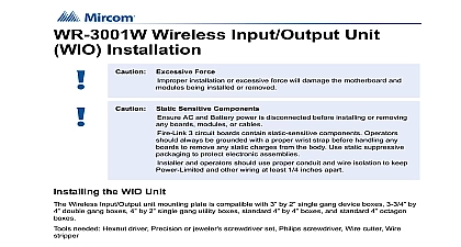
Wireless Extension for Emergency and Fire Alarm System and Operation Manual Rev 2 2021 of Contents Fire Link 3 Wireless Emergency and Fire Alarm System 1 1 Notes 1 3 Wireless Overview 3 Wireless Components 2 Zone Controller ZC 3 Wireless Input Output unit WIO 3 Module and Relay Module 3 Overview 4 Controller Installation the Zone Controller Enclosure 5 Tips 6 dimensions of the Zone Controller 6 installation of the Zone Controller 7 for Wiring 7 8 the Power 9 Power 9 Power 9 Switches 10 the DIP Switches 10 Input Output Unit Installation the WIO Unit 11 Tips 11 12 12 Switches 13 the DIP Switches 13 the Wireless Input Output unit 14 the Notification Appliance to the Wireless Input Output unit 17 Controller Board Terminal Connectors Location 19 of Contents Controller Input Terminals 19 Controller Addressable Loop Terminals 20 Controller Output Terminals 20 20 NAC Wiring to Zone Controllers 21 Controller Relay Wiring to FACP Input Zones 22 SLC Loop Wiring to Zone Controllers 22 and Secutron FACP SLC Loop Wiring to Zone Controllers 24 Indicators and Controls Controller LEDs and Controls Ancillary for ULC 27 27 28 28 Input Output unit LEDs and Buttons 29 29 30 Input Output unit Operation 31 Operation 31 Operation UL 31 Operation ULC 31 Operation while in Trouble Condition 31 Condition 31 Tones 31 Operation while in Alarm Condition UL 32 Operation while in Alarm Condition ULC Dwelling Unit Use Only 32 Switch Settings for each ZC and WIO ID Settings 34 ID Settings 35 A Specifications and Features Warranty and Warning Information of Figures 1 System Components 4 2 Zone Controller Enclosure Dimensions 6 3 Mechanical installation of the Zone Controller 7 4 Zone Controller Mounting Holes Dimensions 8 5 Zone Controller AC and Battery Power Wiring 9 6 Location of Zone Controller DIP Switches and USB port 10 7 DIP Switches on the Zone Controller set to Channel ID 19 and PAN ID 1126 10 8 Parts of the Wireless Input Output unit 12 9 Wireless Input Output unit Mounting Plate Dimensions 12 10 Location of Wireless Input Output unit DIP Switches and Connections 13 11 DIP switches on the Wireless Input Output unit set to Channel ID 19 and PAN ID 1126 14 12 Mounting Plate Front View 14 13 Mounting Plate Back View 15 14 Mounting the Wireless Input Output unit on the Mounting Plate 16 15 Generic Notification Appliance Mounting Plate with End of Line Resistor 17 16 Wiring the Notification Appliance Mounting Plate to WIO unit 18 17 Notification Appliance Mounting Holes Available on the WIO unit 18 18 Zone Controller Board Terminal Connectors 19 19 Zone Controller Inputs 1 4