Mircom LT-856 RAX-LCD Installation and Wiring Manual (English)

File Preview
Click below to download for free
Click below to download for free
File Data
| Name | mircom-lt-856-rax-lcd-installation-and-wiring-manual-english-7140286593.pdf |
|---|---|
| Type | |
| Size | 1.87 MB |
| Downloads |
Text Preview
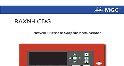
Advanced Life Safety Solutions FX 2000 Annunciator Panel FX 2000 Control System System Normal 01 2011 12 21 AM ANNUNCIATOR Interchange Way ON L4K 5W3 905 660 4655 Fax 905 660 4113 Steve Reynolds Blvd Unit 17 Atlanta GA 30093 1 888 660 4655 Fax 1 888 660 4113 Mircom 2003 in Canada to change without prior notice and Wiring Manual Rev 7.1 2011 of Contents of Contents Us 8 Inquiries 8 Service 8 Support 8 8 Instructions Instructions Switch Settings RAX 1048 Adder Annunciator Chassis 13 IPS 2424 Programmable Input Switches Module 13 RAX LCD Shared Display Chassis 14 and Features Models 15 Models 15 Remote FX 2000 Shared Display LCD Annunciator 15 Adder Annunciator Chassis 48 Display Points 15 Drain for Battery Calculations 16 Specifications 16 Warranty and Warning Information Please Read Carefully 17 to Installers 17 Failures 17 Installation 17 Failure 17 of Replaceable Batteries 17 of Radio Frequency Wireless Devices 18 Users 18 Alarm Initiating Devices 18 18 Notification Appliances 18 Lines 19 of Contents Time 19 Failure 19 Testing 19 and Insurance 19 Warranty 19 Warranty 19 to Void Warranty 20 Procedure 20 of Warranties 20 of Warranty Repairs 20 of Figures and Tables of Figures and Tables 9 1 1 Mechanical Assembly Diagram 9 2 Wiring Diagram 10 3 Annunciator Panel Connections 10 2 Maximum Wiring Run to Last Annunciator 11 4 Annunciator Connections 13 Settings 13 3 Model Descriptions 15 4 of Figures and Tables Introduction FX 2000 remote shared display is the RAX LCD The RAX LCD shared display an exact replica less 16 zone LEDs of the main FX 2000 Fire Alarm Panel display a remote location It is equipped with a large 4 line x 20 character back lit alphanumeric display that uses a simple menu system complete with a directional keypad and switches Enter Menu Cancel and Info The display expands with up to a total of four RAX 1048TZ Annunciator or six IPS 2424 Programmable Input Switches Modules There are five of enclosure available the BB 1001 BB 1002 BB 1003 BB 1008 and BB 1012 which take 1,2,3,8,12 chassis respectively It may also be mounted in the BB 5008 and the BB General Inquiries Customer Service and Technical Support you can contact us Monday to 8 00 A M to 5 00 P M E S T Contact Us General Inquiries Free North America Only Customer Service Free North America Only Free Fax North America Only Fax Technical Support Free North America Only Website Instructions Installation Instructions 1 Backboxes H in A in B in CAN BE MOUNTED STANDARD 4 X 4 BOXES BACKBOX IS SHOWN CHASSIS 1 Mechanical Assembly Diagram RAX 1048 is supplied with the NP 681 Blank Laser Printable Label Sheet RAX 1048 normally displays Initiating circuit status no individual circuit however model RAX 1048TZ will allow individual circuit trouble as well Indicating and relay circuits are not remotely displayed For details see the fire alarm control panel ma