Mircom MIX-4003-R Relay Base Installation Manual

File Preview
Click below to download for free
Click below to download for free
File Data
| Name | mircom-mix-4003-r-relay-base-installation-manual-0536278419.pdf |
|---|---|
| Type | |
| Size | 1.88 MB |
| Downloads |
Text Preview
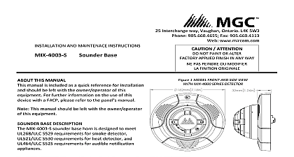
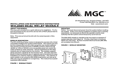
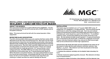
Interchange way Vaughan Ontario L4K 5W3 905.660.4655 Fax 905.660.4113 www mircom com ATTENTION NOT PAINT OR ALTER APPLIED FINISH IN ANY WAY PAS PEINDRE OU MODIFIER FINITION ORIGINALE 1 MODEL FRONT AND SIDE VIEW MIX 4000 SERIES DETECTOR 1 SPECIFICATION temperature range Standby Current Alarm Current Diameter Height wire gauge to 49 to 120 to 93 mA mA 7 3 16 in 1 1 4 in AWG AND MAINTENACE INSTRUCTIONS Relay Base THIS MANUAL manual is included as a quick reference for installation should be left with the owner operator of this For further information on the use of this with a FACP please refer to the panel manual This manual should be left with the owner operator this equipment BASE DESCRIPTION MIX 4003 R relay base is designed to meet UL268 ULC requirements for smoke detector UL521 ULC S530 for heat detector MIX 4003 R must be used with a compatible MGC panel The device can control one independent while using one address MIX 4003 R provides one form C SPDT contact rated 2A at 30Vdc or 0.5A at 125Vac and a compatible panel switch discrete contacts by code command Circuit to the relay contacts are not supervised by the MIX 4003 R supports group activation capability for reaction time Rev 1.1 November 10 2021 COMPONENT 2 RELAY BASE ASSEMBLY COMPONENTS 4 WIRING TABS plate x 3 4 x2 base x25 mm x2 3 MIX 4000 SEREIS DETECTOR series mounting plate in figure 2 is mounted first on the box and all wiring is done on integral screw The connections are apparent and can be inspected before the sounder base itself is Then the enclosure containing the electronics sounder and the detector base can plugged in and This device should be installed as per applicable of the authorities having jurisdiction installing this device seek guidance from the control panel instructions for the device modes and the configuration requirements It is to remove power from SLC and NAC lines performing installation the information in this document to determine the current draw of the devices The total current draw of devices must not exceed the NAC output capacity of panel In all cases the installer should consider the drop to ensure that the last device on the circuit within its rated voltage Please consult fire panel manual for guidance on wire resistance and For maximum strobe operating current please to Table 4 not loop signal circuit field wires around terminals supervision requires wire run to be broken at end Wire run is broken Wrong Wire is looped around terminal 5 DEVICE CONNECTION Wiring must be in accordance with CSA C22.1 Electrical Code Part I Safety Standard for Installations section 32 and or NFPA 70 SYSTEM SUPERVISION FOR ALL TERMINAL TAPS DO USE LOOPED WIRE UNDER TERMINALS BREAK WIRE TO PROVIDE SUPERVISION OF CONNECTIONS PAS UTILISER DE FILS EN BOUCLE SOUS LES BORNES FOURNIR UN BON SUIVI DES CONNEXIONS LA CONTIUIT DES C recommends spacing speaker strobe appliances in with CAN ULC S524 and or NFPA72 mounting plate is compatible with 3 by 2 single gang boxes 3 3 4 by 4 double gang boxes 4 by 2 gang utility boxes standard 4 by 4 boxes and 4 octagon boxes Attach the mounting plate to electrical box with two mounting 8 32 x 3 4 screws Slide down the sounder base enclosure until the blades touch the clips on the mounting plate Secure the mounting plate with securing M3 x25 mm 6 MOUTING DIAGRAM 1 2 3 DETECTOR the detector type and address has be visible from the break the address tab inside the detector base insert it in the outer rim of the base See figures 7 9 DETECTOR ALIGNMENT MARK 7 ADDRESS TAB INSERT tab Numbers 4000 SERIES RELAY BASE SERIES DETECTORS Isolated photoelectric detector Isolated photoelectric detector Rev7 Non isolated photoelectric heat detector Non isolated photoelectric heat detector Rev7 Isolated photoelectric heat detector Isolated photoelectric heat detector Rev7 Isolated heat detector photoelectric detector photoelectric detector Rev7 heat detector detector can then be placed on the top base using the steps figure 8 Position the detector centrally on its adapter base it is level Rotate clockwise applying gentle pressure The detector drop into its keyed location Continue to rotate clockwise a few degrees until the has fully engaged in the adapter base When the detector is firmly engaged check the of the raised reference marks on the detector on the base figure 9 8 MOUNTING DETECTOR clockwise lock counter unlock