Mircom MIX-4020 MIX-4020-ISO Multi-Sensor Installation Manual-English
File Preview
Click below to download for free
Click below to download for free
File Data
| Name | mircom-mix-4020-mix-4020-iso-multi-sensor-installation-manual-english-5682719034.pdf |
|---|---|
| Type | |
| Size | 1.80 MB |
| Downloads |
Text Preview
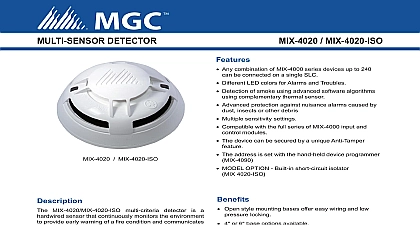
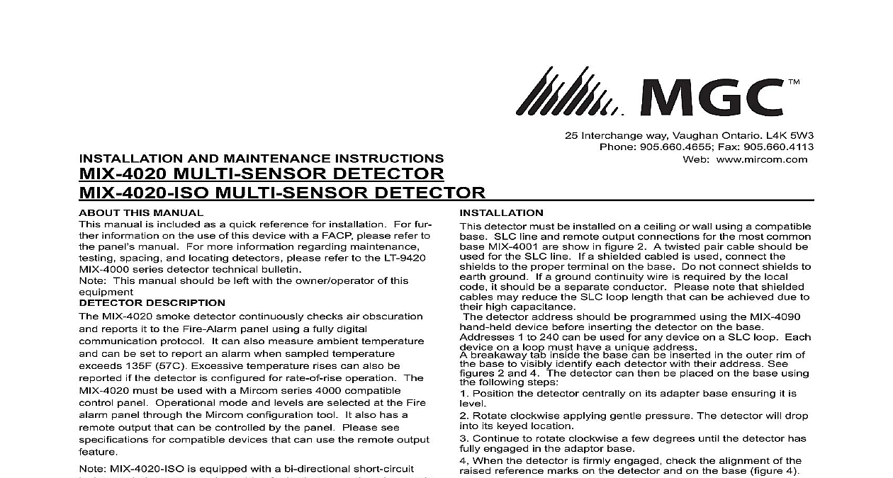
Interchange way Vaughan Ontario L4K 5W3 905.660.4655 Fax 905.660.4113 www mircom com AND MAINTENANCE INSTRUCTIONS MULTI SENSOR DETECTOR MULTI SENSOR DETECTOR THIS MANUAL manual is included as a quick reference for installation For fur information on the use of this device with a FACP please refer to panel manual For more information regarding maintenance spacing and locating detectors please refer to the LT 9420 series detector technical bulletin This manual should be left with the owner operator of this DESCRIPTION MIX 4020 smoke detector continuously checks air obscuration reports it to the Fire Alarm panel using a fully digital protocol It can also measure ambient temperature can be set to report an alarm when sampled temperature 135F 57C Excessive temperature rises can also be if the detector is configured for rate of rise operation The must be used with a Mircom series 4000 compatible panel Operational mode and levels are selected at the Fire panel through the Mircom configuration tool It also has a output that can be controlled by the panel Please see for compatible devices that can use the remote output MIX 4020 ISO is equipped with a bi directional short circuit to help protect against wiring faults that may otherwise result a loop failure installing this device please thoroughly read this manual and to the applicable codes for guidance on location spacing and use Also seek guidance from the compatible control instructions for the device operation modes and the requirements If the detector is used with the remote indicator then the value of the detector must be at least 18V as the indicators not operate below 18V 1 DETECTOR FRONT detector must be installed on a ceiling or wall using a compatible SLC line and remote output connections for the most common MIX 4001 are show in figure 2 A twisted pair cable should be for the SLC line If a shielded cabled is used connect the to the proper terminal on the base Do not connect shields to ground If a ground continuity wire is required by the local it should be a separate conductor Please note that shielded may reduce the SLC loop length that can be achieved due to high capacitance detector address should be programmed using the MIX 4090 device before inserting the detector on the base 1 to 240 can be used for any device on a SLC loop Each on a loop must have a unique address breakaway tab inside the base can be inserted in the outer rim of base to visibly identify each detector with their address See 2 and 4 The detector can then be placed on the base using following steps Position the detector centrally on its adapter base ensuring it is Rotate clockwise applying gentle pressure The detector will drop its keyed location Continue to rotate clockwise a few degrees until the detector has engaged in the adaptor base When the detector is firmly engaged check the alignment of the reference marks on the detector and on the base figure 4 NOTES ON DETECTOR INSTALLATION loop power before installing the detector detector comes with a dust cover to protect the device during and when first installed It is not intended to provide protection against contamination therefore detectors be removed from their base before construction major re or other dust producing work is started Dust covers must removed before the system becomes operational detectors should installed away from normal heat sources Do use in locations where ambient temperature is within 20F 10C the alarm setting Long term ambient temperature should not 120F 49C configured for rate of rise operation do not use heat detectors locations such as an heated building entrance where large swings can be expected detectors are not to be used with detector guards unless the has been evaluated and found suitable for that purpose duplicate terminals are not provided to facilitate monitoring of installation wiring connections and there is no provision to pre looping an unbroken wire around or under a terminal the word and the following or equivalent text in letters not less 2.38 mm 3 32 inch high shall be included on the installation FOR SYSTEM MONITORING FOR TERMINALS Loop AND Remote Device DO NOT USE LOOPED WIRE TERMINALS BREAK WIRE RUN TO PROVIDE MONITOR OF CONNECTIONS Operating Voltage Alarm Current LED on Current Input Wiring Resistance Range no alarm range on all terminals LT to 30VDC LED on LED flashing Ohms to 100F 0C to 37.8C to 93 Non condensing 1 4 Diameter 1 3 4 Height square by 2 1 8 deep box Programmer Detector Base Remote LED to 12 AWG 2 DETECTOR WIRING 3 LOOP WIRING 4 ALIGNMENT MARKS LED Colors and Temperature Steady on Flash Steady on LT Level 1 2 3 4 feet feet feet feet sensitive level sensitive level detection settings 57C with rate of rise as per UL268