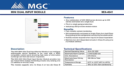
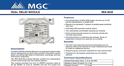
Mircom MIX-4046 Supervised Output Module Data Sheet - English

File Preview
Click below to download for free
Click below to download for free
File Data
| Name | mircom-mix-4046-supervised-output-module-data-sheet-english-1063489275.pdf |
|---|---|
| Type | |
| Size | 1.19 MB |
| Downloads |
Text Preview
SUPERVISED OUTPUT MODULE Any combination of MIX 4000 series devices up to 240 be connected on a single SLC Mounts in a standard 4 square or double gang electrical box Indicating LED provides module status Same device can handle NAC Speakers and Fire applications A single stocked device type covers three application Supports group activation capability for fast reaction time No jumpers or special hardware setting for specific Supervised powered output Speaker 25V 70V Fire phone Can handle Class A or Class B device wiring No external required for class A operation Device automatically selects application mode as by the panel configuration at start up MIX 4046 Supervised Output Module is an intelligent module designed to be used with an MGC control panel providing high rates of information and fast and secure responses MIX 4046 Output Module controls speakers Notification or Fire Phones module is compatible with MGC FT 300A and FH 100A A supervision busy tone is provided for an handset module supports class A or B One circuit rated 2A 24VDC NAC One circuit rated 2A 25VRMS Speaker One circuit rated 0.5A 70VRMS Speaker Fire Phone internal EOL resistor is provided for Class A operation address of each module is set using the MIX 4090 tool module has a panel controlled LED indicator The LED during normal operation and stays ON steadily when device is in alarm condition TO BE USED FOR INSTALLATION PURPOSES INFORMATION IS FOR MARKETING PURPOSES ONLY AND INTENDED TO DESCRIBE THE PRODUCTS TECHNICALLY NUMBER Specifications Operating Value Alarm Current Operating Current Fire Phone Wiring Resistance Range Range on all terminals to 30 VDC LED on with 22K EOL Ohms to 120 0 to 49 to 93 Non condensing to 12 AWG 5 8 x 4 1 4 W x 1 1 8 D square by 2 1 8 deep box Wiring total drop from the power supply output to the devices should not exceed 1.8V This includes the riser drop and the 4046 device line drop If the riser is connected to several MIX 4046 the total riser load current must be used to calculate The following tables provide a useful approximation riser length from power supply to last MIX 4046 16AWG 14AWG 12AWG 34m 175ft line length from MIX 4046 to last device with case riser loss 16AWG 14AWG 12AWG 34m 175ft line wire selection 70VRMS line maximum voltage drop on a 70V line should not exceed 7V from the amplifier to the last speaker to limit power loss to The following tables provide a useful approximation riser length from amplifier to last MIX 4046 16AWG 14AWG 12AWG line length from MIX 4046 to last speaker worst case riser loss 16AWG 14AWG 12AWG TO BE USED FOR INSTALLATION PURPOSES INFORMATION IS FOR MARKETING PURPOSES ONLY AND INTENDED TO DESCRIBE THE PRODUCTS TECHNICALLY 9509 2 of 3 Line Wire Selection 25VRMS line riser length from amplifier to last MIX 4046 16AWG 14AWG 12AWG line length from MIX 4046 to last speaker worst case riser loss 16AWG 14AWG 12AWG Information Output Module Addressable Device Programmer Mount Electrical Box Plate Interchange Way Ontario L4K 5W3 905 660 4655 905 660 4113 Witmer Industrial Estates Falls NY 14305 Free 888 660 4655 Toll Free 888 660 4113 INFORMATION IS FOR MARKETING PURPOSES AND NOT TO DESCRIBE THE TECHNICALLY complete and accurate installation testing and certification refer to technical This document contains intellectual property of Mircom information is subject to change by Mircom without notice does not represent or warrant correctness or completeness relating 9509 2


