Mircom MIX-4050 Sync Module Installation Manual

File Preview
Click below to download for free
Click below to download for free
File Data
| Name | mircom-mix-4050-sync-module-installation-manual-0746592813.pdf |
|---|---|
| Type | |
| Size | 1.50 MB |
| Downloads |
Text Preview
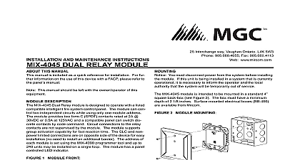
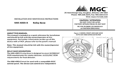
INSTALLATION AND MAINTENANCE INSTRUCTIONS SYNC MODULE Interchange way Vaughan Ontario L4K 5W3 905.660.4655 Fax 905.660.4113 www mircom com This device should be installed as per applicable requirements the authorities having jurisdiction Install the module wiring as indicated by the job drawings and wiring diagrams See figures 3 to 5 Mount the module in the electrical box as shown in figure 2 1 MODULE FRONT Connection 2 MODULE MOUNTING THIS MANUAL manual is included as a quick reference for installation and be left with the owner operator of this equipment DESCRIPTION Mircom MIX 4050 sync module provide a means of controlling synchronizing NAC devices such as horns strobes and horn combinations It is compatible with Mircom 400 series devices is designed to be used with compatible UL or ULC listed Fire or NAC power boosters which can provide a continuous non 24V regulated output during alarm condition The MIX 4050 with either DC filtered or FWR voltage supply and can be to one class A or two Class B lines with a load of up to 3 per line The MIX 4050 uses under 25mA average During when the supply voltage is reversed device current is and will not affect NAC line supervision schemes using resistors to 20 MIX 4050 can be liked together to provide module to synchronization Two stage and ON OFF control of audible is provided at the individual module level Overall strobe or audible status of other linked MIX 4050 will not be affected one or several modules are set to silence condition Sync and controls are electrically isolated which allows linked MIX 4050 operate from different supply sources without compromising fault detection The module to module sync uses an master slave scheme that requires no programming or setting If the device being the current master is switched a new master will take over immediately without creating off sync pulses A LED one the MIX 4050 will indicate which is the master steady on or a slave pulsating Voltage 24V regulated 16 to 33V DC filtered or FWR supply current maximum 25mA average lines current 3A for class A 2 x 3A for class B lines stage and Silence input activation voltage 16 to 33V DC or FWR stage and Silence input current 3.5mA max 33VDC link Internally limited current and voltage Range 32 to 120 0 to 49 10 to 93 Non condensing 4 5 8 x 4 1 4 W x 1 1 8 D 4 square by 2 1 8 deep box or BB 400 Electrical Box range on all terminals 22 to 12 AWG You must disconnect power from the system before installing module If this unit is being installed in a system that is currently it is necessary to inform the operator and the local that the system will be temporarily out of service MIX 4050 module is intended to be mounted in a standard 4 back box see Figure 2 The box must have a minimum of 2 1 8 inches Surface mounted electrical boxes BB 400 available from Mircom LT 6151 rev 1.5 12 2 20 3 SINGLE CLASS A WIRING AUDIBLE AND CONTROL H and H to P1 and C ensure that strobes and turn on and off at the time FIRST STAGE 16 TO 33VDC OPEN IF UNUSED 4 DUAL CLASS B WIRING AUDIBLE AND CONTROL NAC SOUNDING 16 TO 33 V DC FROM THE TERMINAL SIDE FIRST STAGE 16 TO 33VDC OPEN IF UNUSED FROM TERMINAL SIDE 5 SYNC MODULES INTERCONNECTION 20 MODULES MAXIMUM Maximum NAC load Maximum NAC load A panel installation for value panel installation for value Maximum load D2 P2 C2 open not used B B outputs must be to same unit Maximum load module FROM TERMINAL SIDE MODULES INTERCONNECTION IS NOT SUPERVISED FROM TERMINAL SIDE module FROM TERMINAL SIDE LT 6151 rev 1.5 12 2 20