Mircom MIX-4070 Short Circuit Isolator Module Installation Manual

File Preview
Click below to download for free
Click below to download for free
File Data
| Name | mircom-mix-4070-short-circuit-isolator-module-installation-manual-4751283096.pdf |
|---|---|
| Type | |
| Size | 1.17 MB |
| Downloads |
Text Preview
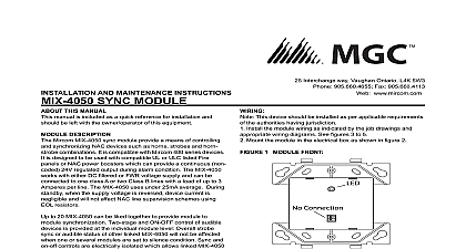
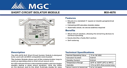
INSTALLATION AND MAINTENANCE INSTRUCTIONS SLC SHORT CIRCUIT ISOLATOR Interchange way Vaughan Ontario L4K 5W3 905.660.4655 Fax 905.660.4113 www mircom com THIS MANUAL manual is included as a quick reference for installation For fur information on the use of this device with a FACP please refer to panel manual This manual should be left with the owner operator of this DESCRIPTION MIX 4070 SLC Short Circuit Isolators enable part of the commu loop to continue operating when a short circuit occurs on it LED indicator blinks in the normal condition and turns on during a circuit condition Only LED of devices next to the short are on for easy identification of faulty SLC section The module automatically restore the entire communication loop to the normal when the short circuit is removed The module is a hard only device that does not require an address There are no lim on number installed on the SLC as long as total loop current limit respected This is a low current device Operating Voltage Current Current Range range on all terminals to 30VDC to 120F 0c to 49C to 93 Non condensing 5 8 x 4 1 4 W x 1 1 8 D square by 2 1 8 deep box Electrical Box to 12 AWG 1 ISOLATOR MODULE WIRING PANEL OR DEVICE PANEL OR DEVICE LT You must disconnect power from the system before installing module If this unit is being installed in a system that is currently it is necessary to inform the operator and the local that the system will be temporarily out of service MIX 4070 module is intended to be mounted in a standard 4 back box see Figure 2 The box must have a minimum of 2 1 8 inches Surface mounted electrical boxes BB 400 available from Mircom The number of devices that may be installed between fault modules will vary depending upon the types of devices being Contact the fire alarm control panel manufacturer for the load ratings of individual devices 2 MODULE MOUNTING This device should be installed as per applicable requirements the authorities having jurisdiction This device shall be connected power limited circuits only Install module wiring in accordance with the job drawings and the diagram in Figure 1 Secure module to electrical box supplied by installer