Mircom MIX-5351APA RAPA HAPA Installation Manual - English
File Preview
Click below to download for free
Click below to download for free
File Data
| Name | mircom-mix-5351apa-rapa-hapa-installation-manual-english-3541986207.pdf |
|---|---|
| Type | |
| Size | 856.30 KB |
| Downloads |
Text Preview
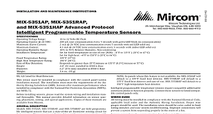
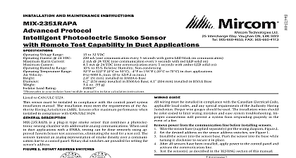
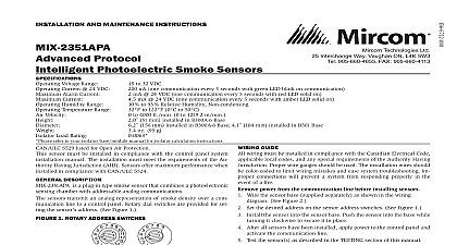
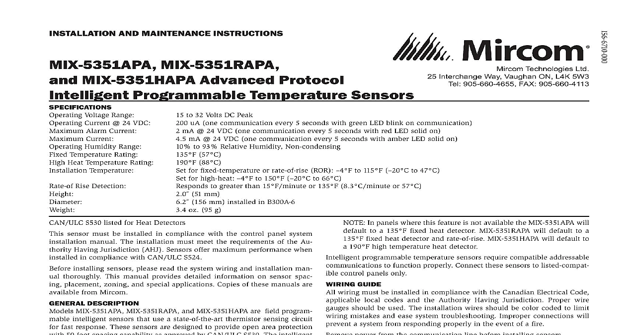
I Technologies Ltd Interchange Way Vaughan ON L4K 5W3 905 660 4655 FAX 905 660 4113 AND MAINTENANCE INSTRUCTIONS MIX 5351RAPA MIX 5351HAPA Advanced Protocol Programmable Temperature Sensors Voltage Range Current 24 VDC Alarm Current Current Humidity Range Temperature Rating Heat Temperature Rating Temperature Rise Detection to 32 Volts DC Peak uA one communication every 5 seconds with green LED blink on communication mA 24 VDC one communication every 5 seconds with red LED solid on mA 24 VDC one communication every 5 seconds with amber LED solid on to 93 Relative Humidity Non condensing 57 88 for fixed temperature or rate of rise ROR to 115 to 47 for high heat to 150 to 66 to greater than 15 or 135 8.3 or 57 51 mm 156 mm installed in B300A 6 oz 95 g NOTE In panels where this feature is not available the MIX 5351APA will to a 135 fixed heat detector MIX 5351RAPA will default to a fixed heat detector and rate of rise MIX 5351HAPA will default to 190 high temperature heat detector programmable temperature sensors require compatible addressable to function properly Connect these sensors to listed compat control panels only GUIDE wiring must be installed in compliance with the Canadian Electrical Code local codes and the Authority Having Jurisdiction Proper wire should be used The installation wires should be color coded to limit mistakes and ease system troubleshooting Improper connections will a system from responding properly in the event of a fire power from the communication line before installing sensors Wire the sensor base supplied separately as shown in the wiring See Figure 2 Set the desired address on the rotary dial switches See Figure 1 Install the sensor into the sensor base Push the sensor into the base turning it clockwise to secure it in place After all sensors have been installed apply power to the control unit and the communication line Test the sensor s as described in the TESTING section of this manual 2 WIRING DIAGRAM Do not loop wire under 1 or 2 Break wire run to connections A OPTIONAL WIRING C0129 11 S530 listed for Heat Detectors sensor must be installed in compliance with the control panel system manual The installation must meet the requirements of the Au Having Jurisdiction AHJ Sensors offer maximum performance when in compliance with CAN ULC S524 installing sensors please read the system wiring and installation man thoroughly This manual provides detailed information on sensor spac placement zoning and special applications Copies of these manuals are from Mircom DESCRIPTION MIX 5351APA MIX 5351RAPA and MIX 5351HAPA are field program intelligent sensors that use a state of the art thermistor sensing circuit fast response These sensors are designed to provide open area protection 50 foot spacing capability as approved by CAN ULC S530 The intelligent sensor can be programmed as either a 135 fixed temperature a rate of rise and 135 fixed temperature sensor or a 190 high tem sensor through the Fire Alarm Control Panel FACP LEDs on each sensor light to provide a local visible sensor indication LED annunciator capability is available as an optional accessory No RA100ZA Rotary dial switches are provided for setting the sensor s See Figure 1 1 ROTARY ADDRESS SWITCHES 0 0 panels offer different feature sets across different models As a re certain features of the Intelligent Programmable Temperature Sensors be available on some control panels but not on others MIX 5351APA and MIX 5351HAPA support Advanced Protocol and CLIP Loop Interface Protocol mode possible features available if supported by the control panel include The sensor LEDs can operate in three ways off and blinking can be set to red green or amber This is controlled by the panel The remote output may be synchronized to the LED operation or con independent of the LEDs Please refer to the operation manual for ULC listed control unit for specific operation of these models Devices are point addressable up to 159 addresses The heat sensor operates as a programmable heat detector 3 FEATURES OF THE HEAT DETECTOR Alignment Notch C2025 00 4 CLEANING THE HEAT DETECTOR to Area RESISTANCE programmable temperature sensors include a tamper resistant ca that prevents removal from the base without the use of a tool Refer to base manual for details on making use of this capability testing notify the proper authorities that the system is undergoing and will temporarily be out of service Disable the system to unwanted alarms sensors must be tested after installation and periodically thereafter Test methods must satisfy the Authority Having Jurisdiction AHJ Sensors maximum performance when tested and maintained in compliance with S536 Test Magnet Model No M02 04 optional Place the optional test magnet against the cover in the magnet test as shown in Figure 3 to activate the test feature The LEDs should latch on within 10 seconds indicating alarm and the panel Reset the detector at the system control panel Direct Heat Method Hair dryer of 1000 1500 watts From the side of the detector direct the heat toward the sensor Hold heat source about 6 inches 15 cm away to prevent damage to cover during testing The LEDs on the detector should light when the temperature at the reaches the alarm setpoint If the LEDs fail to light check the to the detector and the wiring in the detector base Reset the detector at the system control panel that fail these tests may need to be cleaned as described under and retested removing the detector notify the proper authorities that the smoke system is undergoing maintenance and will be temporarily out of the zone or system undergoing maintenance to prevent unwanted Remove the sensor to be cleaned from the system Use a vacuum cleaner or compressed air to remove dust and debris from sensing area Reinstall the detector Test the detector as described in TESTING Reconnect disabled circuits Notify the proper authorities that the system is back on line CLASSIFICATION ratings are for installations which must comply with FM 3210 Fixed RTI of Rise 135 Fixed RTI Fixed RTI INFORMATION Limitations of Fire Alarm Systems go to of Alarm Systems is a registered trademark of Mircom Technologies Ltd STATEMENT device complies with part 15 of the FCC Rules Operation is subject to the following two conditions This device may not cause harmful interference and 2 this device must accept any interference including interference that may cause undesired operation This equipment has been tested and found to comply with the limits for a Class B digital device to Part 15 of the FCC Rules These limits are designed to provide reasonable protection against interference in a residential installation This equipment generates uses and can radiate radio energy and if not installed and used in accordance with the instructions may cause harmful to radio communications However there is no guarantee that interference will not occur in particular installation I