Mircom MIX-FC351AP Installation Manual

File Preview
Click below to download for free
Click below to download for free
File Data
| Name | mircom-mix-fc351ap-installation-manual-9362854017.pdf |
|---|---|
| Type | |
| Size | 1.24 MB |
| Downloads |
Text Preview
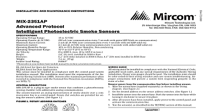
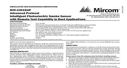
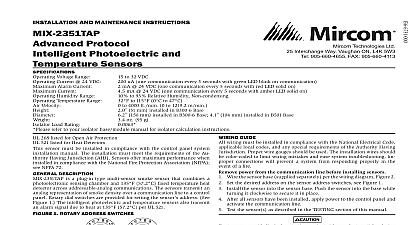
I Technologies Ltd Interchange Way Vaughan ON L4K 5W3 905 660 4655 FAX 905 660 4113 AND MAINTENANCE INSTRUCTIONS Protocol CO and Smoke Sensor Voltage Range Current 24 VDC Alarm Current Current Humidity Range Temperature Range Velocity Load Rating refer to your isolator base module manual for isolator calculation instructions to 32 VDC uA one communication every 5 seconds with green LED blink on communication mA 24 VDC one communication every 5 seconds with red LED solid on mA 24 VDC one communication every 5 seconds with amber LED solid on to 90 Relative Humidity Non condensing to 115 0 to 47 to 4000 ft min 0 to 1219.2 m min 69 mm installed in APB200 series sounder base 175 mm installed in APB200 series sounder bases oz 95 g 2075 listed for Carbon Monoxide 268 listed for Open Air Protection 521 listed for Heat Detectors sensor must be installed in compliance with the control panel sys installation manual For local audible indication of a fire and or monoxide alarm it is recommended to install the multi criteria monoxide CO and smoke sensors into a APB200 series sounder If a local audible device is not used care should be taken to de a proper response plan The installation must meet the require of the Authority Having Jurisdiction AHJ Sensors offer maximum when installed in compliance with the National Fire Protec Association NFPA see NFPA 72 and NFPA 720 For a complete list compatible bases refer to the Base Sensor Cross Reference Chart at DESCRIPTION is a plug in type multi criteria smoke sensor that offers a pho sensing chamber combined with a carbon monoxide CO sensor 57.2 fixed temperature heat detector and infrared IR sensors as as a carbon monoxide dtector The MIX FC351AP also transmits an alarm due to heat 135 per UL 521 sensors transmit an analog representation of smoke and or carbon monox density over a communication line to a control panel Rotary dial switches provided for setting the sensor address See Figure 2 LEDs on the sensor are controlled by the panel to indicate sensor status output is provided for connection to an optional remote LED annunciator RA100Z panels offer different features sets across different models As a result features of the photoelectric sensors may be available on some control but not on others multi criteria CO and smoke sensor supports Advanced Protocol mode possible features available in the multi criteria CO and smoke sensors if by the control unit are The sensor LEDs can operate in three ways off and blinking can be set to red green or amber This is controlled by the panel independent of the LEDs Devices are point addressable up to 159 addresses refer to the operation manual for the UL listed control panel for spe operation The multi criteria CO and smoke sensors require compatible communications to function properly Connect these sensors to control panels only recommends spacing smoke detectors in compliance with NFPA 72 low air flow applications with smooth ceilings space sensors 30 feet apart m For specific information regarding sensor spacing placement and applications refer to NFPA 72 and the System Smoke Detector Ap Guide available from Mircom For specific information regarding detector spacing placement and special applications refer to NFPA 72 720 and the System Connected Carbon Monoxide Detectors Application also available from Mircom GUIDE wiring must be installed in compliance with the National Electrical Code local codes and any special requirements of the Authority Having Proper wire gauges should be used The installation wires should color coded to limit wiring mistakes and ease system troubleshooting connections will prevent a system from responding properly in the of a fire power from the communication line before installing sensors Wire the sensor base supplied separately per the base wiring diagram Figure 1 Set the desired address on the sensor address switches See Figure 2 Install the sensor into the sensor base Push the sensor into the base while it clockwise to secure it in place After all sensors have been installed apply power to the control panel and the communication line Test the sensor s as described in the TESTING section of this manual 1 WIRING DIAGRAM not loop wire under terminal 1 or 2 Break wire run to provide supervision connections The remote output may be synchronized to the LED operation or con A OPTIONAL WIRING 2 ROTARY ADDRESS SWITCHES 0 0 Test Point Alignment Notch 3 FEATURES OF THE FIRE CO DETECTOR Test Point C2043 00 4 CLEANING THE FIRE CO DETECTOR Cover Chamber and Screen place the detector into an alarm condition because the detec algorithms correctly determine a burst of canned smoke is not fire In to perform functional testing of the photoelectric sensor the device be placed into test mode Test mode allows the detector to isolate individual sensors for testing The device can be placed into test mode either of the following methods a Put the device into test mode by holding a test magnet in the magnet area as shown in Figure 3 for 6 12 seconds NOTE If the magnet is held in place for too long the fire alarm test func will be triggered See Magnet Test above Reset the panel and pro with testing the smoke entry portion of the device b Perform smoke entry testing immediately following the magnet test The test initiates an approximately 10 minute period when the detec signal processing software routines are not active in test mode test the smoke detector using one of the tested and ap aerosol smoke products Refer to the manufacturer published instruc for proper use of the canned smoke agent When used properly the smoke agent will cause the smoke detector to go into alarm and approved aerosol smoke products include Fire and Safety Climb 30S PURCHECK CENTURION SOLO A10 TRUTEST SOLO 365 2000 C2044 00 covers provide limited protection against airborne dust particles during Dust covers must be removed before the sensors can sense smoke sensors prior to heavy remodeling or construction RESISTANCE MIX FC351AP includes a tamper resistant capability that prevents re from the base without the use of a tool Refer to the base manual for on making use of this capability testing notify the proper authorities that the system is undergoing and will temporarily be out of service Disable the system to unwanted alarms sensors must be tested after installation and periodically thereafter Test methods must satisfy the Authority Having Jurisdiction AHJ Sensors maximum performance when tested and maintained in compliance with 72 Sensitivity readings are available through the FACP Refer to the turer published instructions for proper use sensor can be tested in the following ways Functional Magnet Test P N M02 04 01 or M02 09 00 This sensor can be functionally tested with a test magnet The test magnet simulates smoke in the sensing chamber testing the sensor and connections to the control panel Hold the test magnet in the magnet test area as shown in Figure 3 The sensor should alarm the panel Two LEDs on the sensor are controlled by the panel to indicate sensor Coded signals transmitted from the panel can cause the LEDs to latch on or latch off Refer to the control panel technical documen for sensor LED status operation and expected delay to alarm N