Mircom Select Series Mounting Bases and Accessories

File Preview
Click below to download for free
Click below to download for free
File Data
| Name | mircom-select-series-mounting-bases-and-accessories-6207849153.pdf |
|---|---|
| Type | |
| Size | 1.01 MB |
| Downloads |
Text Preview
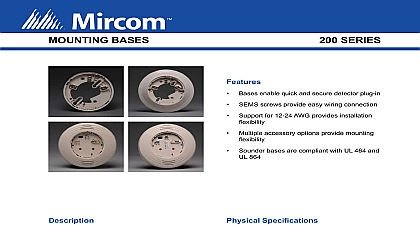
MOUNTING BASES AND ACCESSORIES SERIES Bases enable quick and secure detector plug in SEMS screws provide easy wiring connection Support for 12 24 AWG provides installation flexibility Multiple base formats meet application requirements Standard white color with ivory options UL 268 compliant Canadian models compliant with CAN ULC S529 Mechanical locking feature restricts removal of attached head Base Features Pre wired mounting plate simplifies installation Application driven feature sets Sounder bases both UL 268 and UL 464 compliant Canadian sounder base models compliant with both S529 and CAN ULC S525 Additional terminal connections on Canadian models silence feature Select Series sounder and low frequency sounder are designed for new and existing dwelling unit They offer maximum flexibility in installation and operation to meet or exceed UL 268 and 464 CAN ULC S529 and CAN ULC S525 requirements Select Series low frequency sounder bases are designed meet the NFPA 72 sleeping space requirement to produce a frequency of 520 Hz 10 with a square wave its equivalent B200SR A sounder and LF sounder bases B200SR are with existing sounder base installations Sounder bases adopt the same address as the detector use a unique device type on the loop The Fire Alarm Panel FACP can use that address to command an or a group of sounders to activate The command from the FACP can be tailored to multiple event driven outputs allowing selection of volume tone and group sounder bases System Sensor protocol This enables it to be used as a of the general evacuation signal along with other Sensor AV appliances when connected to a power or FACP output capable of generating the System synchronization pulses Kits meet local code and application requirements Mircom standard 4 and 6 bases as well as specialty base including relay isolator sounder and low frequency options for Select Series detectors standard 4 and 6 bases offer a plug in detector base for use in intelligent systems The 4 base offers a design while the 6 base provides compatibility with wider range of junction boxes the Select Series Junction Box Selection Guide on the page for junction box options Select Series specialty bases support application driven bases B224RB A WH B224RB A IV provide one C contact relay for control of auxiliary functions such as closure and elevator recall The relay can operate in two modes short and long delay The activation time for short delay is 60 ms to 100 ms while the activation time the long delay is 6 sec to 10 sec bases B224BI A WH B224BI A IV allow Line Circuit SLC loop to operate under fault created from a short circuit preventing an entire loop from being disabled The base isolates section of the loop containing the short circuit from the of the circuit and automatically restores when the is corrected TO BE USED FOR INSTALLATION PURPOSES INFORMATION IS FOR MARKETING PURPOSES ONLY AND INTENDED TO DESCRIBE THE PRODUCTS TECHNICALLY Refer to ordering information for agency listing details NUMBER Specifications Color White Color Ivory Range to applicable sensor Operating Temperature Range Range to 93 RH non condensing 17.4 cm Height without sensor 18.8 mm 19 mm 10.2 cm 155 mm 17.4 cm 4.1 cm 4.1 cm lb 145 gm lb 145 gm lb 227 gm lb 272 gm lb 227 gm Gauge AWG 0.823 mm to 12 AWG 3.31 mm AWG 0.823 mm to 12 AWG 3.31 mm AWG 2.08 mm to 12 AWG 3.31 mm AWG 0.823 mm to 12 AWG 3.31 mm TO BE USED FOR INSTALLATION PURPOSES INFORMATION IS FOR MARKETING PURPOSES ONLY AND INTENDED TO DESCRIBE THE PRODUCTS TECHNICALLY 5900 2 of 5 to 32 VDC Spefications B501 IV Voltage Current B300 6 IV B300A 6 B300A 6 IV to 32 VDC Voltage max Current B224BI IV B224BIA WH B224BIA IV to 32 VDC Voltage max Current Current mA max B22RB IV B224RBA WH B224RBA IV Voltage Current Time Time Characteristics to 32 VDC max 1 Short Delay 60 to 100 ms 2 Long Delay 6 to 10 sec ms max coil latching relay Form C contact Rating Rating Voltage Voltage A A A A A VAC VDC VDC VDC VAC VDC VDC VDC 0.35 20ms 0.35 0.75 0.75 B200SR IV B200SRA WH B200SRA IV Supply Electrical Ratings Supply Voltage Current Current Electrical Ratings Operating Voltage Standby Current to 33 VDC VFWR maximum mA maximum Output B200SR LF IV Supply Electrical Ratings Supply Voltage Current Current Electrical Ratings Operating Voltage Standby Current Output to 33 VDC VFWR mA maximum VDC mA maximum 33.0 VDC mA maximum 24.0 VDC mA maximum 16.0 VDC to 32 VDC maximum than 85 dBA minimum measured in a UL reverberant room ULC anechoic room at 10 feet 24 in continuous tone to 32 VDC to applicable sensor specification than 85 dBA minimum measured in a UL reverberant room at 10 feet 24 Volts continuous tone TO BE USED FOR INSTALLATION PURPOSES INFORMATION IS FOR MARKETING PURPOSES ONLY AND INTENDED TO DESCRIBE THE PRODUCTS TECHNICALLY 5900 3 of 5 APB200 IV APB200A WH APB200A IV Supply Electrical Ratings Supply Voltage Current Current Electrical Ratings Operating Voltage Standby Current to 33 VDC VFWR maximum mA maximum at high volume setting 15mA maximum at low volume setting to 32 VDC maximum than 85 dBA minimum measured in a UL reverberant room ULC anechoic room at 10 feet 24 Volts in continuous tone than 75 dBA minimum measured in a UL reverberant room ULC anechoic room at 10 feet 24 Volts in continuous tone Volume Volume APB200 LF IV Supply Electrical Ratings Supply Voltage Current Current High volume setting Current Low volume setting Electrical Ratings Operating Voltage Standby Current Output Volume Volume to 33 VDC VFWR mA maximum VDC mA maximum 33.0 VDC 90 mA maximum 24.0 VDC 140 mA maximum 16.0 VDC mA maximum 33.0 VDC 20 mA maximum 24.0 VDC 25 mA maximum 16.0 VDC to 32 VDC maximum base only refer to applicable sensor specification than 85 dBA minimum measured in a UL reverberant