Cooper-Wheelock NS Series Horn Strobes & NH Series Horns

File Preview
Click below to download for free
Click below to download for free
File Data
| Name | cooper-wheelock-ns-series-horn-strobes-nh-series-horns-8940135762.pdf |
|---|---|
| Type | |
| Size | 681.54 KB |
| Downloads |
Text Preview
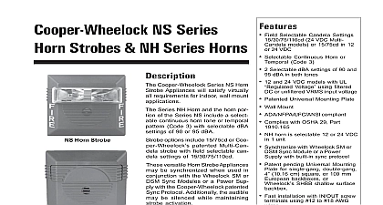
Features Field Selectable Candela Settings 24 VDC Multi models or 15 75cd in 12 24 VDC Selectable Continuous Horn or Code 3 2 Selectable dBA settings of 90 and dBA in both tones 12 and 24 VDC models with UL Voltage using filtered or unfiltered VRMS input voltage Patented Universal Mounting Plate Wall Mount ADA NFPA UFC ANSI compliant Complies with OSHA 29 Part NH horn is selectable 12 or 24 VDC 1 unit Synchronize with Wheelock SM or Sync Module or a Power with built in sync protocol Patent pending Universal Mounting for single gang double gang 10.16 cm square or 100 mm backboxes or SHBB shallow surface Fast installation with IN OUT screw using 12 to 18 AWG and approvals below apply to basic NS Series Strobes and NH Horns In some cases certain may not be listed by certain agencies or listing may be process Consult factory for latest status UL Listed file E5946 ULC Listed files CS243 CS356 FM approved MEA approved file 151 92 E CSFM approved file 7125 NS Series Strobes NH Series Horns Cooper Wheelock Series NS Horn Appliances will satisfy virtually requirements for indoor wall mount Series NH Horn and the horn por of the Series NS include a select continuous horn tone or temporal Code 3 with selectable dBA of 90 or 95 dBA options include 15 75cd or Coo patented Multi Can strobe with field selectable can settings of 15 30 75 110cd versatile Horn Strobe Appliances be synchronized when used in with the Wheelock SM or Sync Modules or a Power Sup with the Cooper Wheelock patented Protocol Additionally the audible be silenced while maintaining activation models of the Series NS and NH designed for maximum perfor reliability and cost effective while meeting or exceeding the requirements of NFPA 72 ANSI and UL Standards 1971 and as well as meeting ADA require concerning photosensitive epi Horn Strobe Horn Indicator of Strobe Lens Notes Strobes are designed to flash once per second minimum over their Range Note that NFPA 72 specifies a flash rate of 1 to 2 flashes per and ADA Guidelines specify a flash rate of 1 to 3 flashes per second All candela ratings represent minimum effective Strobe intensity based on UL 1971 Series NS Strobe products are listed under UL Standard 1971 for indoor use a temperature range of 32 to 120 0 to 49 and maximum humidity 93 2 Series NH horns are listed under UL Standard 464 for audible signal appli Indoor use only Voltage Range is the newest terminology used by UL to identify voltage range Prior to this change UL used the terminology Range Series Horn Strobes NH Series Horns CS 2246 09 01 06 1 of 3 Specifications audible visual notification appliances shall be Cooper Wheelock Series NS Horn Strobe and Series NH Horn appliances or approved equals The Series NS appliances shall and be listed for UL Standard 1971 Emergency Devices for the Hearing Impaired for Indoor Protection Service The Series NH Horn shall be UL Listed under Standard 464 Fire Signaling The horn strobe shall be listed for indoor use and shall meet the require of FCC Part 15 Class B All inputs shall be compatible with standard reverse polarity of circuit wiring by the Fire Alarm Control Panel FACP audible portion of the appliance shall have a minimum of two 2 field selectable settings for levels 90 and 95 dBA and shall have a choice of continuous or temporal Code 3 audible strobe portion of the appliance shall produce a flash rate of one 1 flash per second over Regulated Voltage Range and shall incorporate a Xenon flashtube enclosed in a rugged lens The Series NS shall be of low current design Where wall mount Multi Candela are specified the strobe intensity shall have field selectable settings and shall be per UL Standard 1971 for 15 30 75 110 candela The selector switch for selecting the setting shall be tamper resistant The 15 75 candela strobe shall be specified when 15 UL Standard 1971 Listing with 75 candela on axis is required e g ADA compliance synchronization is required the appliance shall be compatible with Cooper Wheelock DSM Sync Modules or a Power Supply with Cooper Wheelock built in Patented Sync The strobes shall not drift out of synchronization at any time during operation If the module or Power Supply fails to operate i e contacts remain closed the strobes shall to a non synchronized flash rate The appliance shall also be designed so that the signal may be silenced while maintaining strobe activation Series NS Horn Strobes and NH horn shall incorporate a Patented Universal Mounting Plate shall allow mounting to a single gang double gang 4 inch square 100mm European type or the SHBB Surface Backbox If required an NATP Notification Appliance Trimplate be provided notification appliances shall be backward compatible Diagram NEXT EOLR SM DSM OR Audible SYNC MODULE OUT2 IN2 OUT RETURN AND NH APPLIANCES SYNCHRONIZED SM MODULE SINGLE CLASS CIRCUIT WITH AUDIBLE SILENCE AND NH APPLIANCES SYNCHRONIZED DSM MODULE DUAL CLASS CIRCUIT WITH NO AUDIBLE SILENCE NS NH must be set on Code 3 horn to achieve synchronized temporal Code 3 tone to instruction P38983 P83600 respectively 2 of 3 Series Horn Strobes NH Series Horns CS 2246 09 01 06 WARNING CONTACT COOPER FOR THE CURRENT IN SERIES NS 24MCW P84234 NS 12 AND 24 VDC SINGLE MODELS P83600 SERIES AND INFORMATION P82380 ON THESE PROD THESE DOCUMENTS UNDERGO CHANGES IT IS IMPOR THAT YOU HAVE CURRENT IN ON THESE PRODUCTS MATERIALS CONTAIN IMPOR INFORMATION THAT SHOULD BE PRIOR TO SPECIFYING OR IN THESE PRODUCTS IN TOTAL CURRENT REQUIRED BY ALL CONNECTED TO SYSTEM POWER SOURCES FUSE RATINGS ON NOTIFICATION AP CIRCUITS TO HANDLE PEAK FROM ALL APPLIANCES THOSE CIRCUITS COMPOSITE FLASH RATE FROM MUL STROBES WITHIN A PERSON OF VIEW ADDING REPLACING OR CHANGING AP OR CHANGING CANDELA WILL AFFECT CURRENT RECALCULATE CURRENT DRAW TO IN THAT THE TOTAL AVERAGE AND TOTAL PEAK REQUIRED ALL APPLIANCES DO NOT EXCEED RATED CAPACITY OF THE POWER OR FUSES THE VOLTAGE APPLIED TO THESE MUST BE WITHIN THEIR VOLTAGE RANGE INSTALLATION OF 110 CANDELA PRODUCTS IN SLEEPING AR INSTALLATION IN OFFICE AREAS AND SPECIFICATION AND INSTALLA ISSUES THESE APPLIANCES ARE NOT DE TO BE USED ON CODED SYS IN WHICH THE APPLIED VOLTAGE CYCLED ON AND OFF FAILURE TO COMPLY WITH THE INSTAL INSTRUCTIONS OR GENERAL SHEETS COULD RESULT IMPROPER INSTALLATION APPLICA AND OR OPERATION OF THESE IN AN EMERGENCY SITUA WHICH COULD RESULT IN PROP DAMAGE AND SERIOUS INJURY DEATH TO YOU AND OR OTHERS CONDUCTOR SIZE AWG LENGTH AMPACITY SHOULD BE TAKEN CONSIDERATION PRIOR TO DESIGN INSTALLATION OF THESE PROD PARTICULARLY IN RETROFIT IN Ordering Information APPROVALS MEA CSFM FM BFP 15 75 on axis 15 75 on axis