Notifier 1451 2-Wire and 4-Wire Ionization Smoke Detector

File Preview
Click below to download for free
Click below to download for free
File Data
| Name | notifier-1451-2-wire-and-4-wire-ionization-smoke-detector-4912608753.pdf |
|---|---|
| Type | |
| Size | 770.11 KB |
| Downloads |
Text Preview
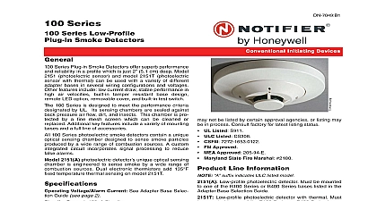
1451 and 4 Wire Smoke Detector System Sensor 400 Series plug in ionization smoke respond quickly to both fast flaming and slow smol fires as required by UL 268 Unipolar dual chamber has the sensitivity needed to quickly detect smoke and stability needed to avoid false alarms Unique dual unipolar sensor Provides exceptional stability Factory preset at 1.9 nominal sensitivity Stable operation up to 1,200 feet per minute 6 meters per air velocities Removable cover for field cleaning Two visible LEDs in standby Sealed against dirt insects and back pressure Three year limited warranty Field metering of detector sensitivity Built in test switch Low standby current Built in tamper resistant feature Designed for direct surface or electrical box mounting 360 field viewing angle of the visual alarm LEDs Easy plug in of the head to base SEMS screws for easy wiring Optional recess mounting Field adjustable sensitivity screening 0.020 0.508 mm openings to contribute to life safety fire protection and property Superior to photoelectric detectors in detecting fires Superior to bipolar detectors in avoiding alarms Operation 400 Series plug in ionization smoke detectors contain a dual source dual unipolar chamber detection design will sense the presence of smoke particles produced by combustion as well as slow smoldering fires Additional features include a blinking LED standby status indicator easily visible alarm indication and provision for convenient test and metering back of the detector is sealed to block back pressure air The chamber is protected by a fine mesh 0.020 0.508 screen to minimize problems with dust dirt and insects cleaning is required it is easy to remove the cover with a tool and obtain access to the screen and chamber to a thorough cleaning 1451 detectors are intended for use with Notifier UL control panels Maximum number of detectors per zone listed in the installation manual for each control panel Easy I 110 Initiating Devices Detector shown with B401B Base install and maintain this detector is designed for direct sur mounting using one of the B400 Series bases listed Easy to wire screw terminals allow fast and simple wiring of IN OUT and remote annunciator connections Notifier control panel specifications for the maximum loop resistance for the particular control panel to be prevent wiring mistakes observe polarities and make cer that each conductor is identifiable A copy of Installation Maintenance Instructions is packaged with each detec For further information refer to NFPA 72 on Fire Detectors Mounting Base Selection Guide is included on page 2 of document Box Selection Guide Box depth is contingent on and wire size Refer to National Electrical Code or local codes for appropriate recommendations Bases and B401B can utilize a single gang 3 1 2 88.9 mm 4 101.6 mm octagonal or 4 square junction box B402B and B406B can utilize a single gang 3 1 2 4 octagonal 4 square 50 mm 60 mm or 75 mm box Base B404B can utilize a 4 octagonal or 4 junction box Specifications voltage mounting base dependent see chart current 120 micro amps 1.9 nominal 0.6 pounds 272 grams 3.2 81.28 mm high 4.0 101.6 mm diameter with bases or 6.2 157.48 mm diameter with flanged Flame retardant white Noryl plastic 32 to 120 0 to 49 6 4 08 Page 1 of 4 range 10 to 93 R H non condensing air velocity 1,200 feet per minute 6 meters per Listings and Approvals listings and approvals apply to the modules specified in document In some cases certain modules or applications not be listed by certain approval agencies or listing may in process Consult factory for latest listing status UL Listed S911 ULC Listed S911 1451A MEA Listed 427 91 E Vol III FM Approved CSFM 7271 1653 108 BSA 1202 88 SA Maryland State Fire Marshal Certificate 2185 Line Information Ionization Detector Must be mounted to one of the Series Bases listed below Remote Annunciator for 2 or 4 wire applications with any System Sensor 400 Series plug in detector Fits U S single gang electrical box Field Test module for all of the System Sensor Series Smoke Detectors Wiring Diagram Wiring Diagram Wiring Diagram Wiring Diagram Base Selection Guide A VDC 8.5 to 35 A ULC C VDC C A VAC VAC VDC to 32 to 32 A ULC A on to 100 to 39 mA AC to 100 Functionality contingent on panel compatibility Must be limited by control panel Contact Ratings Resistive or Inductive 60 power factor load Form a 2.0A at 30VAC DC 0.6A at 110VDC 2.0A at 30VDC 1.0A at 125 VAC ULC model designation 2 of 4 DN 1154 A 6 4 08 of to and and are cleaning 6 4 08 Page 3 of 4 is a registered trademark of Honeywell International Inc Noryl a registered trademark of GE Plastics a subsidiary of General Electric by Honeywell International Inc All rights reserved Unauthorized use this document is strictly prohibited document is not intended to be used for installation purposes We try to keep our product information up to date and accurate cannot cover all specific applications or anticipate all requirements specifications are subject to change without notice more information contact Notifier Phone 203 484 7161 FAX 203 484 7118 in the U S A 4 of 4 DN 1154 A 6 4 08