Notifier 30-2056B Infrared Flame Detector

File Preview
Click below to download for free
Click below to download for free
File Data
| Name | notifier-30-2056b-infrared-flame-detector-9456728130.pdf |
|---|---|
| Type | |
| Size | 788.82 KB |
| Downloads |
Text Preview
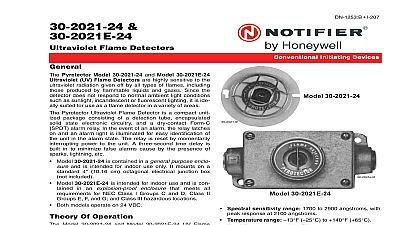
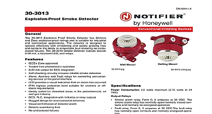
30 2056B Flame Detector Pyrotector Model 30 2056B IR Flame Detector is a unitized package containing an IR detection cell state electronics and dry Form C SPDT contacts for and fault conditions The detector is engineered to to the nominal 4.45 micron band of infrared radia which is commonly known as the CO2 spike See Figure A characteristic of burning hydrocarbons is the emission of high levels of IR radiation in this narrow portion of radiation spectrum On the other hand extraneous light that are capable of triggering an alarm in other types fire detectors emit very low levels of radiation in this range concentrating on this narrow band of the spectral range is highly specific to burning hydrocarbons combined the use of optical filters to discriminate against most background radiation from a variety of sources hot objects the Model 30 2056B is able to provide high level of reliable fire detection while being relatively to false alarm signals detector is compatible with most 24 volt filtered DC four fire alarm control panels High immunity to false alarms caused by lightning arc x rays and sunlight Compatible with standard alarm systems Remote test feature assures reliable response Explosion proof and watertight housing for use in a variety applications Pyrotector Model 30 2056B Infrared Flame Detector is for use in applications where the occurrence of or arc welding within the protected area can cause ultraviolet fire detector to register a false alarm The is virtually immune to actuation caused by lightning welding and most other extraneous light sources It is suited for use in a variety of both indoor and outdoor in nearly any ambient lighting environment the full range of artificial lighting The housing is watertight and dust tight and conforms to NEMA and NEC requirements Typical applica that can use the 30 2056B flame detector include Hydrocarbon processing plants Hazardous storage facilities Offshore oil platforms Airport facilities Fuel loading racks RESPONSE TIME response time of the detector depends on the size of the the rate of propagation fire type and the proximity of the to the detector The average response time to a one foot gasoline fire at 50 feet is less than 6 seconds I 208 Initiating Devices 1 Sensitivity Range for Hydrocarbon Fires TESTING detector has a remote test feature that allows the opera to test the detection circuitry for proper function and also the optical integrity of the lens from a location that is from the detector installation To initiate a test the places the system in bypass and simply presses a 7 13 11 Page 1 of 4 switch usually located at the control panel This actuates integral IR radiation source that is mounted inside the resulting in the simulation of a flickering fire Upon of the simulated fire the detector latches into an condition to indicate that it is operating correctly The can then be reset by interrupting power to the unit a minimum of 0.3 second The detector will fail remote if 50 of the detection range is lost LED is illuminated during an alarm condition to serve as integral visual alarm indicator Proof of successful remote test is activa of alarm relay of Vision detector has a nominal 80 degree cone of vision How the detector can be rotated up to 360 so that the area be protected is within its cone of vision Proper aiming and coverage is recommended to ensure hazardous protection See Figure 2 below of Operation electromagnetic emission of a hydrocarbon fire is char by a strong band in the 4.2 to 4.7 micron range band known as the CO2 spike is caused by the emis of energy generated by excited CO2 molecules Since is the dominant feature of the spectral emission for fires the IR sensor is designed to respond with sensitivity to radiant energy at the 4.45 micron range detection cell is a specially developed pyro electric cell an integral optical filter window which restricts incoming to the wavelength band 4.2 to 4.7 microns the CO2 The detection cell responds by generating a signal is proportional to the radiation being detected electronic circuitry that processes the signal from the cell checks for flicker response ignoring signals spurious light sources The flicker rate and count are factory set for levels characteristic of a fire A flickering signal that exceeds the preset threshold will result in actuation of the alarm relay voltage 18 to 32 VDC with maximum ripple 0.5 at 60 to 120 Hz current Standby 1 watt Alarm 3.5 watts maxi contact rating Alarm and Fault Relays have Form C and are rated for 2.0 at 30 VDC sensitivity range 4.2 to 4.7 microns time Detector responds to a 1 foot square gaso fire at zero axis to detector in less than 6 seconds at 50 of vision 80 degrees nominal with sensitivity to 70 40 2 degrees of zero axis Figure 2 shows cone vision of sensor range Operating to 167 to Storage to 185 to 85 See Figure 3 Explosion proof and watertight anodized alumi Explosion proof Class 1 Div 1 Groups C D Class II 1 Groups E F G Watertight NEMA 4 Conduit fitting 3 4 NPT Female and vibration meets MIL STD 810C vibration 2 of Vision of Detector represents the maximum distance for a given fire sensitivity increases as angle of incidence decreases 2 of 4 DN 5517 B1 7 13 11 3 in Inches mm assure maximum detector sensitivity the lens must be free of dirt or other contaminating film detector should be tested regularly If it fails a test clean lens and test again If the detector fails again it should be and replaced The defective detector should be sent the factory for repairs Remove power to the detector before cleaning the lens or external wiring Procedure checkout of the system using the oi feature a flame or flickering IR source should be performed on a regularly basis to ensure that the system is operating prop The period between checkouts will depend on the levels potential hazard involved in the environmental conditions In general the more frequent the checkouts greater the reliability of the system extinguishing equipment connected to the system must disabled when the system is tested to prevent unwanted of this equipment To test the system point a test at each unit or activate the remote test feature for five to seconds Alarm response indicates that the viewing win is clean and that all electronic circuitry is operational of response may indicate reduced sensitivity due to on the viewing window a damaged sensor or circuitry problems installer should provide a 3 4 inch conduit to the appro point where the detector is to be located This conduit be grounded All wiring cables to the detectors must be and the shields must be grounded The use of con seals is recommended prevent ignition of a hazardous atmosphere do not the cover while power is applied to the detector Provide a shielded wiring cable 16 to 22 AWG recom with a minimum of 6 inches service loop at the junc box Be certain that all wiring complies with the local wiring If necessary consult a qualified official Connect the external wiring to the detector Place the cover on the detector Be sure the O ring is in and that no wires are trapped To ensure proper coverage of the surveillance area ori the detector so that the lens faces the center of the area be protected Clean the oi ring and sensor window with a clean lint cloth Wet with alcohol only 7 13 11 Page 3 of 4 is a registered trademark of Honeywell International Inc by Honeywell International Inc All rights reserved Unauthorized use this document is str