Notifier APS-6R 6 0 Amp Auxilary Power Supply

File Preview
Click below to download for free
Click below to download for free
File Data
| Name | notifier-aps-6r-6-0-amp-auxilary-power-supply-4761859320.pdf |
|---|---|
| Type | |
| Size | 792.11 KB |
| Downloads |
Text Preview
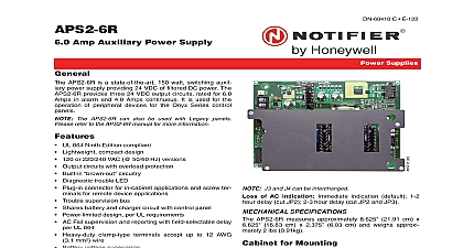
APS 6R Amp Auxilary Power Supply APS 6R is a state of the art 150 watt switching auxiliary supply providing 24 VDC of filtered DC power The provides two 24 VDC output circuits each rated for Amps in alarm and 2.0 Amps continuous It is used for the of peripheral audible visual devices alarm signaling for the NOTIFIER AM2020 AFP1010 NFS 3030 AFP 400 AFP 300 AFP 200 System 5000 and 500 control panels Lightweight compact design Forward topology Unique design magnetic flux sensed converter elimi switching technology need for opto coupler feedback 120 or 240 VAC 50 60 Hz field selectable Wide input voltage range 90 132 VAC 180 264 VAC High efficiency Output circuits with overload protection Built in circuitry Diagnostic trouble LED Plug in connector for in cabinet applications and screw ter for remote device applications Shares battery and charger circuit with control panel Power limited design per UL requirements Surface mount technology conserves panel space AC Fail supervision with field selectable delay per UL 864 Heavy duty clamp type terminals accept up to 12 AWG 3.1 wire AND OPERATION used with the CAB 3 or CAB 4 Series CAB A3 A4 C3 C4 or D3 D4 the APS 6R mounts to a CHS 4 CHS 4L mounting chassis If more than one APS 6R is nec to satisfy Audible Visual DC power requirements con additional APS 6R power supplies together as described the Installation Instruction Manual When used with the the APS 6R mounts in the lower portion of the cabi where batteries would normally mount BB 17 required used with the System 500 only one APS 6R may be in the right most position in the cabinet Laboratories requires that all Signaling Appli be approved for use with the selected control system to voltage operating range criteria Use only those appli listed for use with the associated control system Refer Device Compatibility Document 15378 with AM2020 AFP1010 NFS 3030 NFS 640 AFP 400 AFP 300 AFP 200 System 5000 and 500 control panels E 121 Supplies 15.558 cm high x 4.25 11.43 cm wide x 3.0 7.62 deep at protruding edge 2.25 5.715 cm deep at box on opposite side SPECIFICATIONS primary input power TB1 120 VAC 120 VAC 60 Hz A 240 VAC cut JP1 240 VAC 50 Hz 1.2 A secondary input power TB3 TB3 1 TB3 2 VDC output power TB2 Total 6.0 A 4.0 A continuous 1 TB2 1 TB2 2 or J1 3.0 A 24 VDC power lim Circuit 2 TB2 3 TB2 4 or J2 3.0 A 24 VDC power F1 AC supervision 250 VAC 4.0 A 3 AG F2 supervision 32 VAC 10.0 A 3 AG supervision bus J3 output Form A contact open J4 input Form A contact open collector J3 and J4 can be interchanged of AC indication Immediate indication default 8 delay cut JP2 16 hour delay cut JP2 and JP3 SPECIFICATIONS APS 6R in its enclosure measures approximately 6 cm x 4 10.16 cm x 3 7.62cm FOR MOUNTING Series Use CHS 4 and CHS 4L chassis for AFP1010 NFS 3030 NFS 640 AFP 400 AFP 300 System 5000 control panels 500 Can mount one APS 6R if the face module card such as an ICE 4 is not installed 08 20 09 Page 1 of 2 For AFP 300 and AFP 400 control panels up to one APS 6R An option module without expan card is allowed backbox Mount up to one APS 6R in the lower of the box where batteries mount A BB 17 battery is required LINE INFORMATION 24 volt filtered power supply 120 220 VAC input 12 24 VDC end of line relay Four module chassis Four module chassis low profile Listings and Approvals listings and approvals below apply to the basic APS 6R In cases certain modules may not be listed by certain agencies or listing may be in process Consult fac for latest listing status UL S624 ULC CS118 CS733 CBP696 Vol IX FM Approved AFP 200 AFP 300 400 AFC 600 NFS AFP 1010 AM2020 NFS 3030 System 500 Sys 5000 CSFM 7315 0028 190 7165 0028 214 NFS 3030 NFS2 3030 7170 0028 216 7170 0028 223 NFS 3030 NFS2 3030 MEA 195 97 E Vol II 447 99 E AFC 600 317 01 E 345 02 E NFS 3030 232 02 E NFS2 APS 6R to the Chassis is a registered trademark of Honeywell International Inc by Honeywell International Inc All rights reserved Unauthorized use this document is strictly prohibited document is not intended to be used for installation purposes We try to keep our product information up to date and accurate cannot cover all specific applications or anticipate all requirements specifications are subject to change without notice more information contact Notifier Phone 203 484 7161 FAX 203 484 7118 in the U S A 2 of 2 DN 5952 A1 08 20 09