Notifier B616LP Installation Instructions

File Preview
Click below to download for free
Click below to download for free
File Data
| Name | notifier-b616lp-installation-instructions-0465897123.pdf |
|---|---|
| Type | |
| Size | 945.09 KB |
| Downloads |
Text Preview
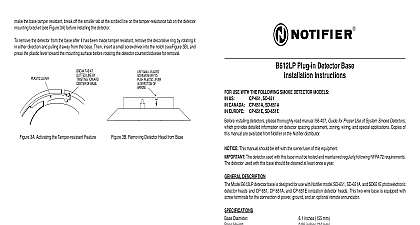
B616LP PLUG IN DETECTOR BASE INSTALLATION INSTRUCTIONS USE WITH THE FOLLOWING SMOKE DETECTOR MODELS US CANADA CP 651A SD 651A EUROPE CP 651E SD 651E SD 651 installing detectors please thoroughly read manual I56 407 Guide for Proper Use of System Smoke Detectors provides detailed information on detector spacing placement zoning wiring and special applications Copies of manual are available from Notifier or through the Notifier distributor For installations in Canada refer to CAN4 Standard for the Installation of Fire Alarm Systems and CEC Part 1 Sec 32 This manual should be left with the owner user of this equipment The detector used with this base must be tested and maintained regularly following NFPA 72 require The detector used with this base should be cleaned at least once a year DESCRIPTION B616LP plug in detector base is used with Notifier model CP 651 CP 651A and CP 651E ionization detector and SD 651 SD 651A and SD 651E photoelectronic detector heads The capability of plugging these detectors a variety of special bases makes them more versatile than equivalent direct wired models B616LP base is intended for use in 2 wire systems with screw terminals provided for power and relay contact con These bases MUST be current limited by the system control panel in the alarm state Diameter Height inches 157 mm inches 24 mm lb 130 g square box with or without plaster ring Min Depth inches octagon box Min Depth inches octagon box Min Depth inches mm box mm box mm box Temperature Range 0 to 49 32 to 120 US and Canadian Installations Humidity Range to 60 14 to 140 European Installations to 93 Relative Humidity RATINGS includes base and detector Voltage Ripple Voltage Capacitance Ratings VDC Volts peak to peak Maximum VDC Minimum VDC Maximum Maximum 12 Clintonville Rd Northfield CT 06472 1652 203 484 7161 V Minimum at 16 mA V Maximum at 100 mA current MUST be limited to 100 mA maximum by the control panel RATINGS Ratings Contact Ratings or Inductive 60 power factor Load C Voltage Time Time 30 VAC DC 110 VDC 125 VAC VDC Minimum Seconds Maximum Seconds Maximum Canadian installations relay contact ratings are 2.0A 30 VAC DC detector base mounts directly to 3 1 2 inch and 4 octagon boxes and 4 inch square boxes with or plaster rings mount remove the decorative ring by turning it in ei direction to unhook the snaps then separate the ring the base Install the base to the box using the supplied with the junction box and the appropriate slots in the base Place the decorative ring on the base then turn in either direction until the snaps in place see Figure 1 ON cid 13 NOT cid 13 NOT cid 13 1 Mounting Base to Box GUIDELINES wiring must be installed using the wire sizes specified by the National Electrical Code and all applicable local codes the authority having jurisdiction The conductors used to connect smoke detectors to control panels and accessory should be color coded to reduce the likelihood of wiring errors Improper connections can prevent a system from properly in the event of a fire signal wiring the wiring between interconnected detectors it is recommended that the wire be no smaller than 18 Wire sizes up to 12 gauge may be used with the base For best system performance the power and loop should be twisted pair and installed in separate grounded conduit to protect the loop against extraneous electrical detectors and alarm system control panels have specifications for allowable loop resistance Consult the control manufacturer specifications for the total loop resistance allowed for the particular model control panel being before wiring the detector loops INSTRUCTIONS system supervision For terminals 2 3 and 5 do not use looped wire under terminals Break wire run to provide supervision of connections POWER LOOP CONTACT AUXILIARY FORM C POWER LOOP A OPTIONAL WIRING 2 Typical Wiring Diagram connections are made by stripping insulation from the end of the wire sliding the bare end of the wire under the plate and tightening the clamping plate screw Use the strip gauges molded into the inside and underside of base for ease of wiring to terminals 1 through 5 and to terminals 12 through 14 respectively zone wiring of the detector base should be checked before the detector heads are installed in them To make this this base contains a special spring type shorting jumper After a detector base is properly wired and mounted an electrical box make sure that the jumper spring is in contact with the base of Terminal 3 This temporary connec shorts the positive in and positive out leads and permits the wiring of the loop to be checked for continuity all the detector bases have been wired and mounted and the loop wiring has been checked the detector heads be installed in the bases The shorting spring in the base will disengage automatically when the detector head is from the base DO NOT remove the shorting spring since it reengages as the detector head is turned into the completing the circuit FEATURE Do NOT use the tamper resistance feature if the XR2 Removal Tool will be used detector base includes a tamper resistance feature that prevents removal of the detector without the use of a tool make the detector tamper resistant break off the tab on the detector base shown in Figure 3A and then install the remove the detector from the base once the tamper resistance feature has been activated place a small bladed into the small hole on the side of the base and push plastic lever away from the detector head see Figure This will allow the detector to be rotated counterclockwise for removal Head removal after the tamper resistant capability has been activated first requires removal of the decorative tamper resistance can be defeated by breaking and removing the plastic lever from the base However this perma disables the tamper resistant capability LEVER TAB AT LINE BY TOWARD OF BASE SMALL BLADED TO PLASTIC LEVER DIRECTION OF 3A Activating Tamper resistance Feature 3B Removing Detector Head from Base LIMITATIONS OF SMOKE DETECTORS smoke detector used with this base is designed to activate and initiate emergency action but will do so only when in conjunction with an authorized fire alarm system This detector must be installed in accordance with NFPA stan 72 detectors will not work without power AC or DC powered smoke detectors will not work if the power supply cut off for any reason detectors will not sense fires which start where smoke does not reach the detectors Smoldering fires do not generate a lot of heat which is needed to drive smoke up to the ceiling where the smoke detector is usu located For this reason there may be large delays in detecting a smoldering fire with either an ionization type de or a photoelectronic type detector Either one of them may alarm only after flaming has initiated which will gener the heat needed to drive the smoke to the ceiling from fires in chimneys in walls on roofs or on the other side of a closed door may not reach the smoke detector alarm it A detector cannot quickly detect or sense at all a fire developing on another level of a building For this detectors shall be located on every level and in every bedroom within a building detectors have sensing limitations too Ionization detectors and photoelectronic detectors are required to fire tests of the flaming and smoldering types This is to ensure that both can detect a wide range of fires Ioniza detectors offer a broad range of fire sensing capability but they are somewhat better at detecting fast flaming fires slow smoldering fires Photoelectronic detectors sense smoldering fires better than flaming fires which have little any visible smoke Because fires develop in different ways and are often unpredictable in their growth neither type of is a