Notifier MIB Media Interface Board

File Preview
Click below to download for free
Click below to download for free
File Data
| Name | notifier-mib-media-interface-board-2036814597.pdf |
|---|---|
| Type | |
| Size | 1.22 MB |
| Downloads |
Text Preview
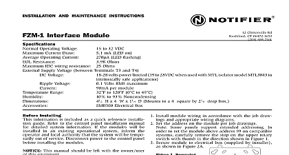
12 Clintonville Road CT 06472 484 7161 484 7118 Fax Manual is a trademark of NOTIFER 1994 B cid 24 cid 19 cid 21 cid 24 cid 24 cid 29 cid 20 cid 28 cid 27 cid 16 cid 19 cid 24 cid 26 General 1 Related Documentation 1 Diagnostic Indicators 2 Installing the MIB 3 The Media Interface Board for Wire MIB W 4 The Media Interface Board for Fiber MIB F 5 The Media Interface Board for Wire and Fiber MIB WF 6 Interface Board PN 50255 B1 03 12 98 Interface Board PN 50255 B1 03 12 98 Media Interface Board MIB provides a means for connecting the AM2020 Fire Alarm Control Panel the Intelligent Network Annunciator INA the Reporting Terminal NRT and nodes to 127 cid 135 5 cid 135 1 7 cid 140 There are types of MIBs available the MIB W MIB F and MIB WF The MIB W is used connect nodes with twisted pair wire The MIB F is used to connect nodes with cable The MIB WF is used to connect twisted pair wire to fiber or fiber to wire at any node in the network obtain a complete understanding of the MIB features and related products or to familiar with functions in general make use of the documentation noted in 1 The NOTIFIER document DOC NOT chart provides the current document Fire Alarm Panel Control System Crystal Display LCD 80 Driver Modules LDM Reporting Terminal NRT Alarm Multiplex Network Annunciator INA XP Series Transponder System Zone Coder UZC 256 Installation Document CCM 1 Adaptor Module UDACT Universal Digital Communicator Transmitter Field Charger and Application Manual Graphics Annunciator System Installation Manual Installation Document MPS TR Supply Installation Operator Instructions Device Compatibility Document Interface Board MIB Fire Panel AFP 200 Requirements for AM2020 AFP1010 RPT Interface Board NIB 96 Interface TPI 232 Control Manual Evaluation Tool MET 1 Fire Panel AFP 300 AFP 400 Series Product Installation Fire Alarm Warden Charger Installation Instructions Auxiliary Power Supply Battery Charger 1 Related Documentation cid 19 cid 21 cid 18 cid 20 cid 21 cid 18 cid 28 cid 27 Interface Board PN 50255 B1 03 12 98 QWHUIDFH RDUG Indicators MIB has diagnostic indicators which aid in troubleshooting and assist the installer connecting the system Refer to Table 2 for a list of diagnostic indicators and their Refer to Figures 1 a and 1 b for the two possible configurations of indicators when the MIB is receiving data from on Port A when the MIB has not received valid from NOTI on Port A HI to indicate the MIB W Port A is set high threshold N A on MIB F MIB WF when a reconfiguration on is in progress when the MIB is transmitting data to HI to indicate the MIB W Port B is set high threshold N A on MIB F MIB WF when the MIB has not received valid from NOTI on Port B when the MIB is receiving data from on Port B Not on all MIB revisions 2 Identifying Indicators cid 20 QGLFDWRU RFDWLRQV Interface Board MIB PN 50255 B1 03 12 98 the MIB QWHUIDFH RDUG install the MIB board on the SIB within an AM2020 AFP1010 system place the over the SIB NET and connect P1 on the MIB to P2 on the SIB Connect P2 on MIB to J6 on the SIB Using the four standoffs and screws supplied secure the to the SIB NET as shown in Figure 2 cid 21 QVWDOOLQJ WKH 0 RQ WKH 6 install the MIB board on the INA place the MIB over the INA and connect P1 on the to J1 on the INA Connect P2 on the MIB to J2 on the INA Using the four and screws supplied secure the MIB to the INA as shown in Figure 3 7KH 1HWZRUN 5HSRUWLQJ 7HUPLQDO cid 11 157 cid 12 LV VKLSSHG ZLWK D 0 LQVWDOOHG cid 17 cid 22 QVWDOOLQJ WKH 0 RQ WKH 1 Interface Board MIB PN 50255 B1 03 12 98 QWHUIDFH RDUG Media Interface Board for Wire MIB W twisted pair wire medium programmable data thresholds to the 127 cid 135 5 cid 135 1 7 cid 140 manual for wiring length and threshold coupling provides electrical isolation between nodes Kbaud transmission rate Style 4 Class B operation or NFPA Style 7 Class A operation terminal wiring with strain relief service connector feeds signal directly through in the event that power be removed from a node is regenerated at each node wiring consecutive MIB W boards note that wiring may enter or exit at Port A Port B as shown in Figure 4 MIB W port to port wiring is not polarity sensitive use of Port A or Port B is arbitrary A MIB W may be connected to any of the devices MIB WF MIB W For information regarding these devices refer to the NAM 232 and Repeater manuals in the Related Documentation Table of this manual LULQJ IURP WKH 0 cid 16 WKDW LV LQVWDOOHG RXWVLGH WKH EXLOGLQJ cid 29 H FHHG cid 20 cid 19 cid 19 cid 19 P cid 11 cid 22 cid 21 cid 27 cid 19 IW cid 17 cid 12 cid 17 0XVW EH LQ FRQGXLW cid 17 FURVV DQ SRZHU OLQHV cid 17 IDXOW IHHG cid 16 VZLWFKHV DQG 6 cid 21 cid 12 cid 17 WR WKH IRU cid 23 7KH 0 cid 16 Interface Board MIB PN 50255 B1 03 12 98 Media Interface Board for Fiber MIB F QWHUIDFH RDUG Kbaud transmission rate fiber optic medium is regenerated at each node is immune to all environmental noise isolation prevents ground loops Style 4 Class B or Style 7 Class A operation 127 cid 135 5 cid 135 1 7 fiber optic medium type 62.5 125 micrometers multimode Wavelength 1 820 nanometers Use standard 850 nm fiber ST Style ST is a registered trademark of AT T connecting consecutive nodes repeaters note that fiber cable must exit one board transmit TX and enter the next node repea