Notifier NCB-EL and NCB-FL Router

File Preview
Click below to download for free
Click below to download for free
File Data
| Name | notifier-ncb-el-and-ncb-fl-router-9067381452.pdf |
|---|---|
| Type | |
| Size | 1.74 MB |
| Downloads |
Text Preview
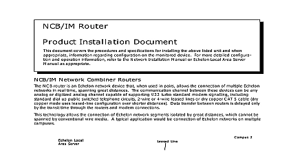
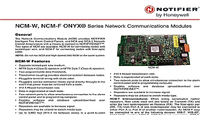
NCB EL and NCB FL Router Installation Document document covers the procedures and specifications for installing the above listed unit s and when information regarding configuration on the monitored device For more detailed configura and operation information refer to the Network Installation Manual or Echelon Local Area Server as appropriate and NCB FL Series Network Combiner Routers routers are Echelon network devices that when used in pairs allow you to connect multiple Echelon networks real time spanning great distances Communication between two NCB EL routers is via an Ethernet to Lonworks connection that uses CAT 5 Ethernet cross over cable Communication between two NCB FL routers is via an Ethernet Fiber to Lonworks connection that uses fiber optic wire runs Ethernet or Fiber Ethernet or Fiber Ethernet or Fiber Ethernet or Fiber Ethernet or Fiber 2 2 2 2 2 Local Local Local Local Local Server Server Server Server Server 1 1 1 1 1 Application of NCB Routers routers allow you to connect Echelon network segments isolated by great distances that cannot be spanned conventional wire media Maximum wire lengths are listed in the NCB Wiring Distance Limitations Table on 4 and should be considered the ABSOLUTE MAXIMUM In many cases where special care is not taken to the specified wire from electrical noise moisture etc reliable long term operation cannot be sustained at wire lengths Communication EL and FL and NCB FL routers allow multiple LonWorks networks to be connected in real time covering distances campus wide to global these routers use Internet Protocol IP for data transport Communication between via NCB router units is live delayed only by the transit time through the integral routers and Ethernet The NCB EL uses standard CAT5 cross over cable and the NCB FL uses dedicated fiber optic cable the NCB EL NCB FL Router routers are always used in pairs EL with EL and FL with FL with one at each end of the Ethernet path Initial router configuration is handled by a set of DIP switches on the front of each router labeled Switches one through six are not used switches seven and eight are used to configure the router for the of network media being used 10Base2 not used for this application 10BaseT used the NCB EL or AUI used for the NCB FL The NCB reads the DIP switch settings at or after you press the RESET button These switches are used to set the following 51895 Rev A ECN 01 683 ECN 01 683 ECN 01 683 ECN 01 683 ECN 01 683 51895 NCB EL and NCB FL Router Installation Rev A 2 12 2002 Used Leave Up Port not used DIP Switch Settings For detailed information on NCB EL NCB FL router configuration to the manufacturer documentation included with the product and NCB FL Routers two routers are similar in function to the NCB IM Physically they differ from NCB IM routers in that they are routers and they communicate over Ethernet instead of a telephone line The 10BaseT and AUI ports for the connection to the Ethernet network Only one port can be used at any one time LEDs LEDs LEDs LEDs LEDs Used Used Used Used Used LEDs LEDs LEDs LEDs LEDs SMX T SMX T SMX Transceiver SMX T SMX T Portortortortort P P P P Daughterboard Daughterboard Daughterboard Daughterboard Daughterboard DIP Switches DIP Switches DIP Switches DIP Switches DIP Switches Connector Connector Connector Connector Connector used used used used used Connector Connector Connector Connector Connector PUI PUI PUI PUI Portortortortort 24VDC IN 24VDC IN 24VDC IN 24VDC IN 24VDC IN Router Motherboard NCB module NCB module NCB module NCB module NCB module PUI PUI PUI PUI Port F F F Fiber F Fiber Adapter 51895 NCB EL and NCB FL Router Installation Rev A 2 12 2002 Status LEDs yellow Activity LED ACT indicates a packet has been passed by the router red Error Indicates one of three things Always on a diagnostic error has occurred Slow flash or always on insufficient configuration information is present Quick flash insufficient IP configuration information Power indicates when power is present for the router Network LEDs RX yellow Ethernet Receive indicates when a packet has been detected on the Ethernet port red Flashes for two seconds when the Control Neuron receives a Wink Network Management com TX green Ethernet Transmit indicates when a packet is transmitted on the Ethernet port CSVC and RSVC Buttons Hardware reset for the entire NCB router Service button for the router Neuron processor Service button for the router module Installation Requirements NCB EL Network Combiner Module SMX Echelon network transceiver NCB Power Supply 24 Volt DC 400mA center POSITIVE outer NEGATIVE Ethernet cross over cable for a direct connection or a standard Ethernet cable otherwise must be supplied customer NISCAB 5 HSP 121B Surge Suppressor Installation Requirements NCB FL Network Combiner Module SMX Echelon network transceiver CentreCOM Fiber Optic Transceiver with provided extension cable NCB Power Supply 24 Volt DC 400mA center POSITIVE outer NEGATIVE HSP 121B Surge Suppressor Bidirectional fiber optic cable must be supplied by customer NISCAB 5 Series Power Supply Requirements NCB EL and NCB FL require 24 VDC 0.050 A nominal and battery backup in accordance with local code It can be powered by any power limited filtered 24 VDC source as appropriate for your area for with fire protective signaling units Power connections are made via plug in screw terminals The NCB power supply unit requires 115 VAC 60Hz primary power UPS Uninterruptable Power Supply for use with fire protective signalling units is for each unit 51895 NCB EL and NCB FL Router Installation Rev A 2 12 2002 Type Type Distance phone line switched telephone circuits leased line line telephone circuits dry contact grade CAT5 copper pair 22 24 AWGNote 1 to 8,000 ft data grade copper pairs CAT5 heavier than normal such as 18 gauge or better to lower resistanceNote 2 to 20,000 ft to 18 gauge THHN power wire not twisted to 4,000 ft to NCB EL direct Ethernet crossover cable to NCB EL with ENIC HUB CAT5 EThernet cable 300 600 ft total fiber with ST connector Wiring Distance Limitations Table 1 1 1 1 Unless specifically stated otherwise all wire described is twisted unshielded and protected from electrical noise to the same extent 1 network wiring would be if run in the same areas 2 2 2 2 The technical description for wire types normally specifies the wire gauge for instance wire specified as CAT 5 is normally 22 or 24 2 It takes a special effort to obtain wire that meets the electrical specifications capacitance characteristic impedance velocity factor the attenuation and is a lower gauge wire and technically the wire at that point would no longer be 5 Jobs using the NCB at these wire distances should be approved by Notifier prior to purchase ft ft the Network Transceiver on NCB Series Routers routers require an SMX network transceiver to connect to the local Echelon network segm