Notifier SLC-IM Signaling Line Circuit Inte- gration Module

File Preview
Click below to download for free
Click below to download for free
File Data
| Name | notifier-slc-im-signaling-line-circuit-inte-gration-module-8652490713.pdf |
|---|---|
| Type | |
| Size | 884.87 KB |
| Downloads |
Text Preview
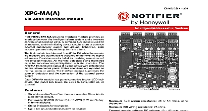
SLC IM Line Circuit Inte Module Signaling Line Circuit Integration Module SLC IM a communication link between a VESDAnet network a Fire Alarm Control Panel FACP SLC loop via the High Interface HLI VHX 1420 HFS It allows mapping of and faults from VESDA detectors onto FACP monitor addresses The SLC IM translates VESDAnet protocol SLC protocol enabling VESDA detector events on the to be annunciated by an FACP SLC IM Communicates with the VESDAnet via an RS 232 connec Supervises the connection to the VHX 1420 HFS HLI Provides 159 FlashScan monitor module addresses that be mapped to events from VESDA detectors using the configuration tool Provides individual alarm annunciation from VESDA E VEA addressable sampling points Uses seven user defined FlashScan monitor module for each programmed VESDA detector plus one monitor module address for VESDAnet wiring Supports up to 22 VESDA detectors on one SLC loop Supports Style 4 and Style 6 configurations on the network The SLC IM cannot monitor VESDA devices with higher than 247 SLC IM interface is listed with ONYX Ninth edition NFS2 3030 NFS2 640 NFS 320 SLC IM is compatible with the following VESDA detectors VESDA VLC VESDA VLF VESDA VLI VESDA VLP VESDA VLS VESDA E VEA VESDA E VEP VESDA E VEU Power input 24 VDC Input current 100 mA 24 VDC The SLC IM must be powered by a UL1481 and or UL regulated power limited battery backed VDC power supply For Canadian installation the SLC IM must be powered a ULC listed regulated 24 VDC power output Fire Systems Control Unit or a ULC listed regulated 24 VDC supply for fire application Temperature 0 to 49 32 120 Relative Humidity 93 non condensing at 32 It is recommended that this product be installed in an envi with a normal room temperature of 15 27 C 60 80 F and Codes SLC IM complies with the following standards and NFPA 72 National Fire Alarm Code UL 864 9th Edition Control Units for Fire Alarm Systems UL 2017 1st Edition General Purpose Signaling Devices Systems CAN ICES 003 CSA C22.1 CAN ULC S527 11 3rd Edition Standard for Control for Fire Alarm Systems ULC S524 06 S561 03 and Approvals listings and approvals apply to the modules specified in document In some cases certain modules or applications not be listed by certain approval agencies or listing may in process Consult factory for latest listing status UL ULC S635 6 9 17 Page 1 of 2 SLC IM Configuration Tool Information ORDERED FROM NOTIFIER Signaling Line Circuit Integration Module Includes board and RS 232 cable PN 75583 for connection to Download VESDAnet Network Interface Card See Includes DB 9 cable for connection to SLC IM UBS 1R Cabinet required SLC IM Order for black UBS 1R for red Dimensions 12.22 L X W X 2.75 H 31.04 cm L X 23.44 cm W X 6.99 cm H detailed information about required components see the Programming and Operation Manual and the SLC IM Document SUPPLIED BY CUSTOMER with available COM port on which to run the SLC IM tool System Architecture ONYX and ONYXWorks are registered trademarks and is a trademark of Honeywell International Inc Windows a registered trademark of Microsoft Corporation VESDA is a registered and Xtralis is a trademark of Xtralis Pty Ltd by Honeywell International Inc All rights reserved Unauthorized use this document is strictly prohibited document is not intended to be used for installation purposes We try to keep our product information up to date and accurate cannot cover all specific applications or anticipate all requirements specifications are subject to change without notice more information contact Notifier Phone 203 484 7161 FAX 203 484 7118 2 of 2 DN 60755 C cid 129 6 9 17